Sample preparation

a sample and sample technology, applied in the field of preparation of samples, can solve the problems of unsuitable for further processing, slow and time-consuming all these methods, and achieve the effect of simple and robus

Active Publication Date: 2009-03-31
FEI CO
View PDF12 Cites 37 Cited by
  • Summary
  • Abstract
  • Description
  • Claims
  • Application Information

AI Technical Summary

Benefits of technology

[0009]An object of the invention is to provide simple and robust methods to extract TEM or STEM samples from substrates. The samples can then be processed on the probe or placed onto sample holders for a TEM or STEM within a vacuum chamber or outside a vacuum chamber.
[0011]In another embodiment, a sample is removed from a substrate within a vacuum chamber by electrical attraction to a probe, and the sample is placed into a TEM or STEM sample holder in the vacuum chamber, thereby eliminating need to weld the sample to the probe or to the sample holder, and eliminating the requirement to remove the sample from the vacuum chamber for placement in a sample holder.

Problems solved by technology

Although the method of Robinson does not destroy the entire wafer, the hole in the wafer after the plug is removed renders it unsuitable for further processing, because the hole will harbor contaminants.
All these methods are slow and time consuming.

Method used


Image

  • Sample preparation
  • Sample preparation
  • Sample preparation

Examples


Embodiment Construction

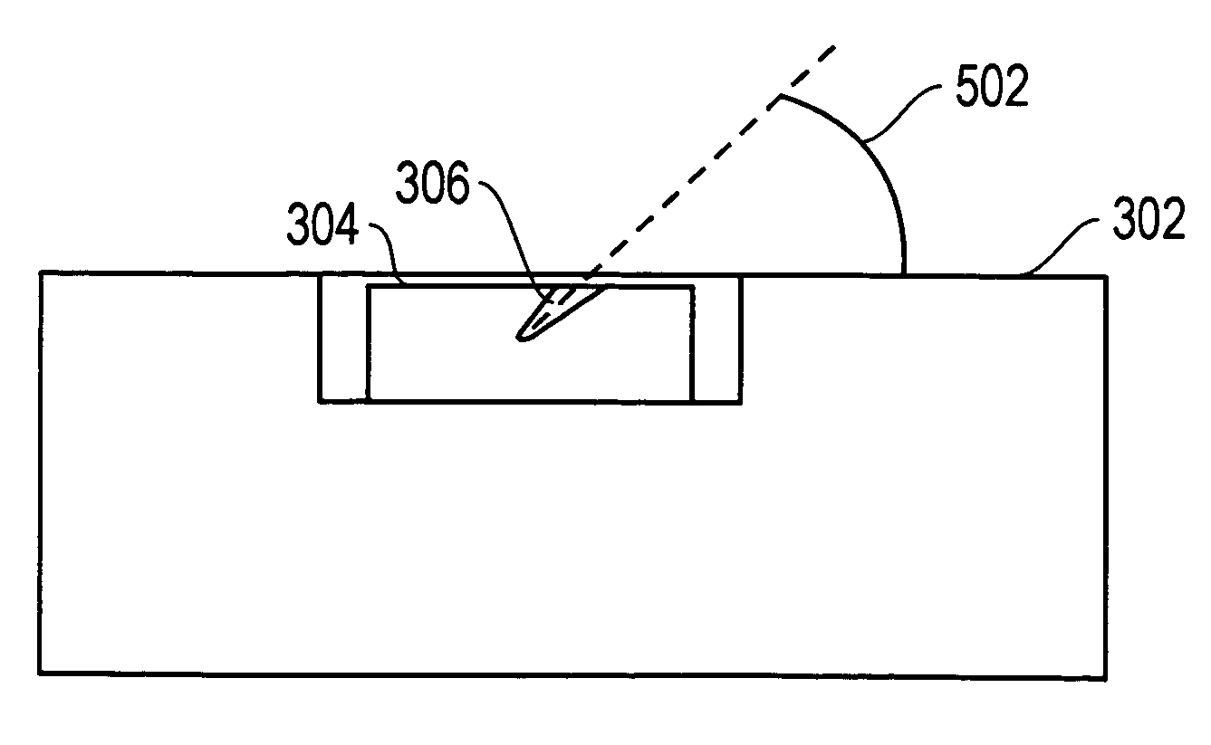
[0030]This disclosure relates to novel methods to remove small chunks of material from a substrate. This method could be used for an ex-situ or in-situ lift out of chunks or lamella.

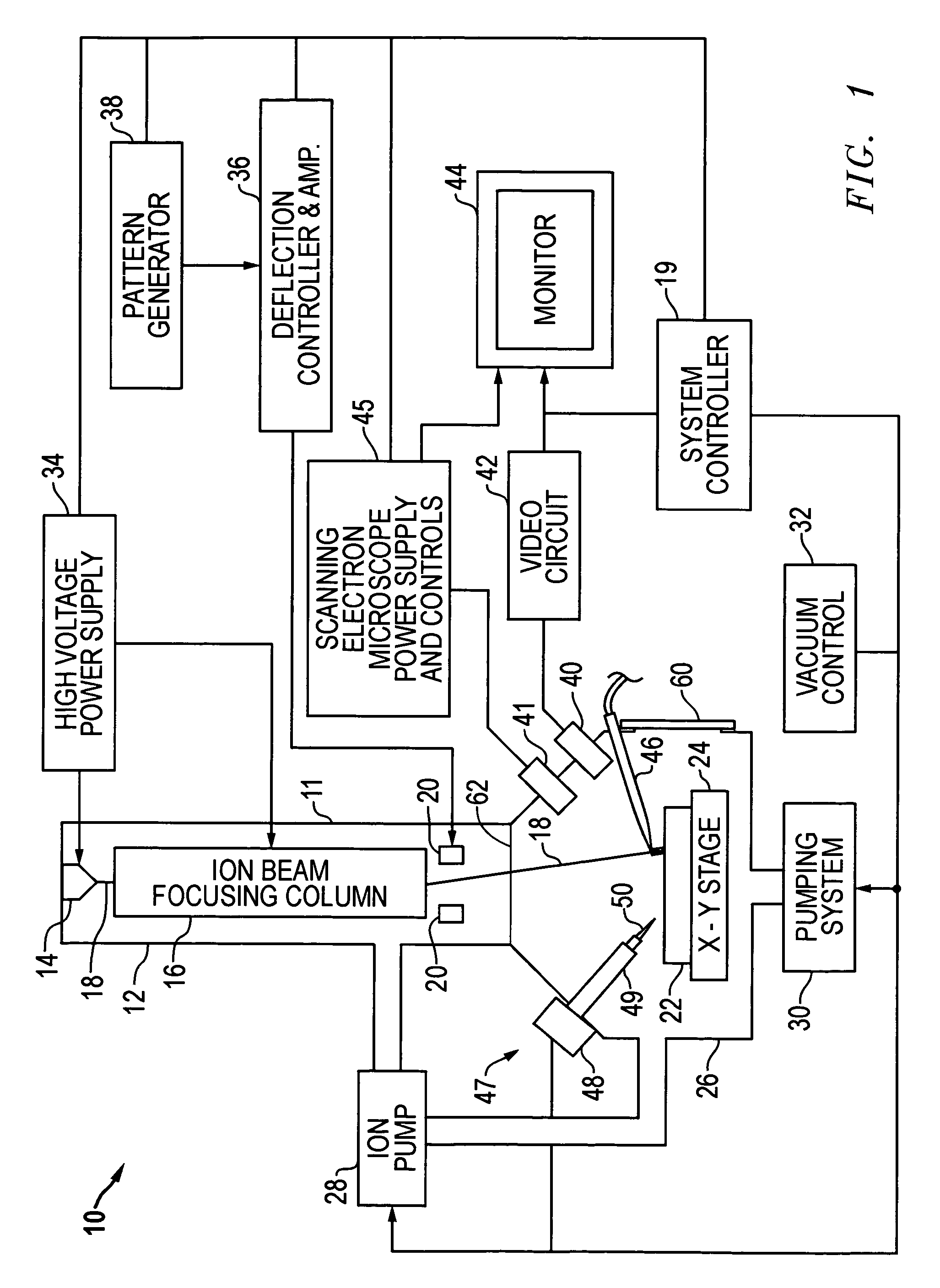
[0031]FIG. 1 shows a typical ion beam system, focused ion beam (FIB) system 10, suitable for practicing the present invention. FIB system 10 includes an evacuated envelope 11 having an upper neck portion 12 within which are located a liquid metal ion source 14 and a focusing column 16 including extractor electrodes and an electrostatic optical system. Other types of ion sources, such as multicusp or other plasma sources, and other optical columns, such as shaped beam columns, could also be used, as well as electron beam and laser system.

[0032]An ion beam 18 passes from liquid metal ion source 14 through ion beam focusing column 16 and between electrostatic deflection means schematically indicated at deflection plates 20 toward sample 22, which comprises, for example, a semiconductor device positioned on ...


PUM

PropertyMeasurementUnit
thickaaaaaaaaaa
thickaaaaaaaaaa
pressureaaaaaaaaaa

Abstract

Methods of extracting a TEM sample from a substrate include milling a hole on the sample and inserting a probe into the hole. The sample adheres to the probe, and can be processed on transferred while on the probe. In another embodiment, the sample is freed from a substrate and adheres to a probe by electrostatic attraction. The sample is placed onto a TEM sample holder in a vacuum chamber.

Description

TECHNICAL FIELD OF THE INVENTION[0001]The present invention relates to preparation of samples for transmission electron microscopes and scanning transmission electron microscopes.BACKGROUND OF THE INVENTION[0002]Electron microscopy provides significantly higher resolution and greater depth of focus than optical microscopy. In a scanning electron microscope (SEM), a primary electron beam is focused to a fine spot that scans the surface to be observed. Secondary electrons are emitted from the surface as it is impacted by the primary beam. The secondary electrons are detected, and an image is formed, with the brightness at each point of the image being determined by the number of secondary electrons detected when the beam impacts a corresponding spot on the surface.[0003]In a transmission electron microscope (TEM), a broad beam impacts the sample and electrons that are transmitted through the sample are focused to form an image of the sample. The sample must be sufficiently thin to all...

Claims


Application Information

Patent Timeline
Patent Type & Authority Patents(United States)
IPC IPC(8): G21K5/10
CPCG01N1/286G01N1/32G02B21/32G01N2001/2833Y10T428/24355H01J2237/31745G01N2001/2886
Inventor AGORIO, ENRIQUETANGUAY, MICHAELROUDIN, CHRISTOPHEHONG, LIANGJORDAN, JAYHENRY, CRAIGDARUS, MARK
Owner FEI CO
Why Eureka
Try Eureka