Method for the manufacture of an X-ray tube cathode filament

a cathode filament and x-ray tube technology, which is applied in the manufacture of electrode systems, manufacturing tools, electric discharge tubes/lamps, etc., can solve the problems of cathode filament becoming brittle at the position of these solder zones, reducing the flexibility of the legs, and reducing the efficiency of the x-ray production. , to achieve the effect of reducing the risk of legs breaking relative to each other and ensuring the stability

Active Publication Date: 2009-04-14
GE MEDICAL SYST GLOBAL TECH CO LLC
View PDF12 Cites 4 Cited by
  • Summary
  • Abstract
  • Description
  • Claims
  • Application Information

AI Technical Summary

Benefits of technology

[0009]In an embodiment of the invention, these problems are resolved by the manufacture, according to a disclosed method, of a single-piece cathode filament in which the thickness of the legs may differ from that of the body. Since the filament obtained in an embodiment of the invention is a single-piece filament, any risk of breakage of the legs relative to the body of the filament is generally avoided. Furthermore, since the thicknesses of the legs and of the body are independent, these thicknesses can be modified in order to make legs that are flexible in relation to the body. Thus, when the filament undergoes expansion, the legs may spread apart outwards. It is therefore possible to have a plane elongation of the body of the filament that does not modify the distance between the cathode and the anode facing it. The cathode filament that it is proposed to make is such that the legs have sufficient flexibility to absorb the deformations of the body of the filament subjected to expansion.

Problems solved by technology

Variations of more than 10 micrometers in the position of one of these elements relative to its expected position can have a deleterious effect on the strict control of X-ray production.
This expansion can cause a break in the filament.
Not only does the soldering method entail a delicate operation but it also causes the cathode filament to become brittle at the position of these solder zones.
There is a risk that the filament will break at the position of these solder zones during an expansion.
The mechanical resistance of the body is diminished, causing it to undergo shifts.
If the body is deformed uncontrollably, the filament can no longer be used.
The prior art cathode filaments are therefore not satisfactory.
A filament having its body soldered to two legs risks breakage at the position of the solder zones when the filament undergoes expansion.
There is a risk that the single-piece filament will get deformed during expansion, modifying the anode-cathode distance.
This is incompatible with efficient operation of the X-ray tube that contains it.

Method used


Image

  • Method for the manufacture of an X-ray tube cathode filament
  • Method for the manufacture of an X-ray tube cathode filament

Examples


Embodiment Construction

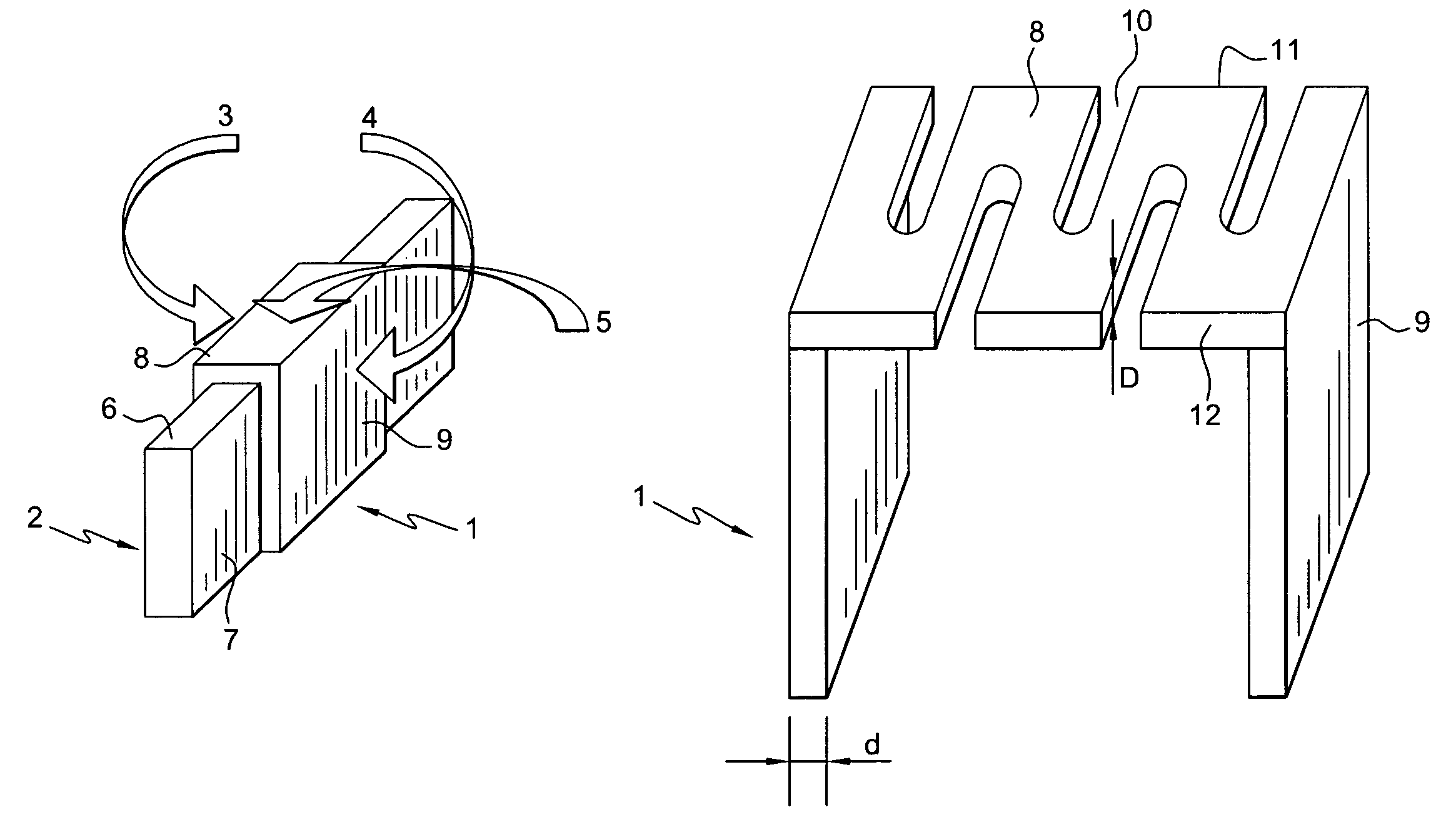
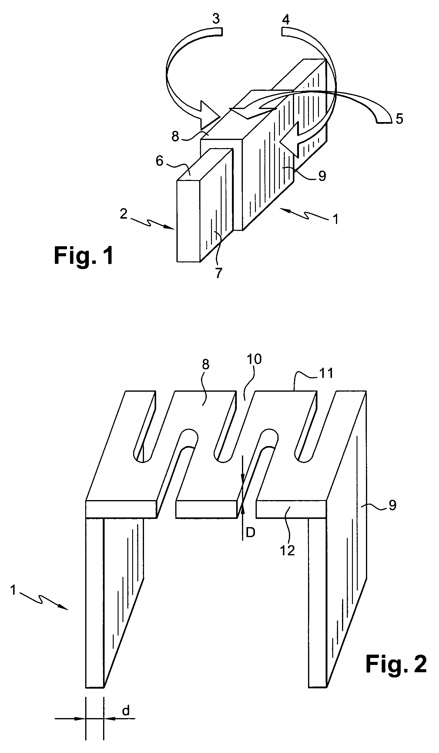
[0014]In an embodiment of the invention, it is proposed to make a cathode filament by plasma spraying. Plasma spraying is a thermal spraying process. A product that is solid, melted or softened by means of a heat source is sprayed in the form of fine particles on a surface prepared beforehand. The combustion energy from a plasma jet is used for this purpose. The plasma is an ionized medium, i.e., a medium constituted by mixture of ions, electrons and neutral species that may or may not be excited. To carry out the plasma spraying, a torch comprising two electrodes is used. The torch takes the form of a conical cathode within a cylindrical anode forming a nozzle. An inert gas such as argon flows between the two electrodes where it is ionized to form a plasma. A tube is used to introduce the material to be sprayed in powder form into the plasma jet. The material to be sprayed is itself carried by a neutral gas. The sprayed particles reached the substrate in a highly melted state, at h...


PUM

PropertyMeasurementUnit
thicknessaaaaaaaaaa
thicknessaaaaaaaaaa
temperatureaaaaaaaaaa

Abstract

A method for the manufacture of a cathode filament of an X-ray tube and an X-ray tube formed by the method wherein the filament has at least two legs and one body, the filament being a single-piece filament. Spraying at least one material on a support by plasma spraying or by another deposition technique to obtain the filament molded on the support and separating the filament obtained from the support. The filament obtained has a variable thickness and a variable composition. The thicknesses of the legs and of the body as well as the composition of the filament can be modified according to the user's needs.

Description

CROSS-REFERENCE TO RELATED APPLICATIONS[0001]This application claims the benefit of a priority under 35 USC 119(a)-(d) to French Patent Application No. 03 51033 filed Dec. 12, 2003, the entire contents of which are hereby incorporated by reference.BACKGROUND OF THE INVENTION[0002]An embodiment of the present invention relates to a method for the manufacture of an X-ray tube cathode filament. More specifically, an embodiment of the invention relates to a method that can be used to obtain a single-piece cathode filament. An embodiment of the invention also relates to an X-ray tube provided with a cathode filament of this kind.[0003]An embodiment of the invention can be applied to X-ray tubes and particularly to tubes used in mammography, in devices used to study the vascular system or in scanners. In medicine, the device used generally as a cathode that emits electron beams is a cathode filament. At least one anode is positioned facing the cathode filament. The electrons emitted by th...

Claims


Application Information

Patent Timeline
Patent Type & Authority Patents(United States)
IPC IPC(8): B23P17/00B05D5/12H01J1/15H01J9/04H01J35/06
CPCH01J9/04H01J35/06Y10T29/49982Y10T29/49799Y10T29/49885Y10T29/4981H01J35/064
Inventor LEMARCHAND, GWENAELPENATO, JEAN-MARIE
Owner GE MEDICAL SYST GLOBAL TECH CO LLC
Why Eureka
Try Eureka