Power amplifier
a power amplifier and power supply technology, applied in the direction of rf amplifiers, high frequency amplifiers, gain control, etc., can solve the problems of high susceptibility to device variations, low controllability of idle current, and complicated control circuits, so as to improve idle current controllability, stable temperature characteristics, and unsusceptible to device variations
- Summary
- Abstract
- Description
- Claims
- Application Information
AI Technical Summary
Benefits of technology
Problems solved by technology
Method used
Image
Examples
first embodiment
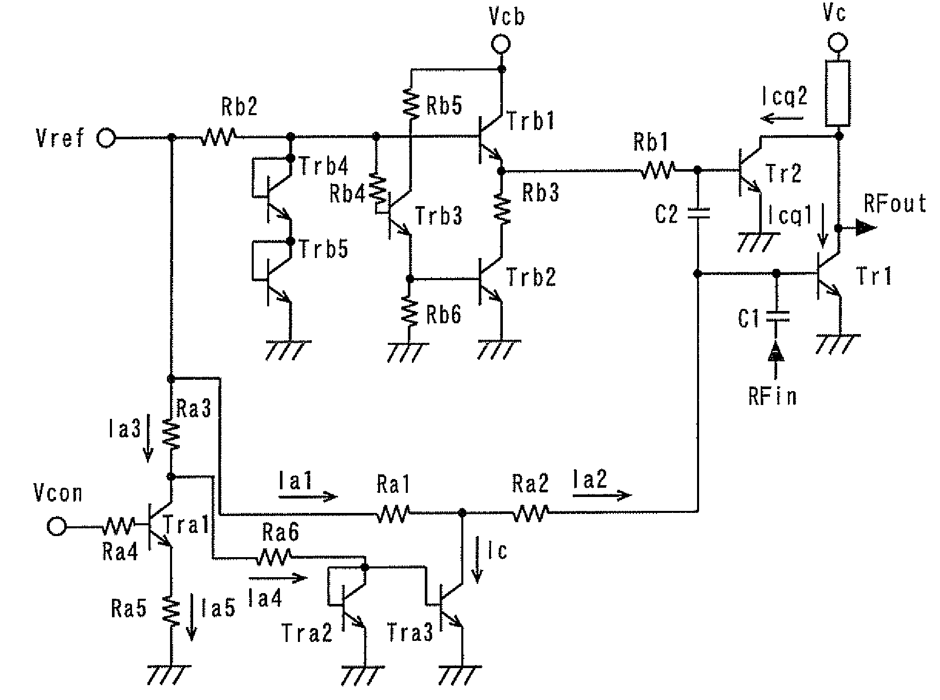
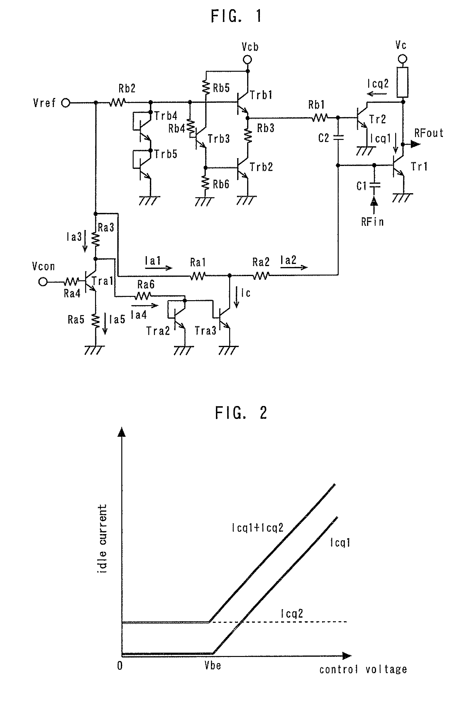
[0039]FIG. 1 is a circuit diagram showing a power amplifier according to a first embodiment of the present invention. Tr1 denotes a first amplifying device; Tr2, a second amplifying device; Vc, a collector power supply terminal of the amplification stage constituted by the first and second amplifying devices Tr1 and Tr2; Vcb, a collector power supply terminal of a bias circuit; Vref, a reference terminal to which a reference voltage (ordinarily 2.8 to 2.9 V) is externally applied; and Vcon, a control terminal to which a control voltage is externally applied. Trb1 to Trb5 and Tra1 to Tra3 denote GaAs-HBTs. Rb1 to RbG and Ra1 to Ra6 denote resistors. An input matching circuit and an output matching circuit are omitted.
[0040]An RF signal input from a terminal RFin is input to the base (input terminal) of the first amplifying device Tr1 via a capacitor C1 of the input matching circuit. The first amplifying device Tr1 amplifies the RF signal and outputs from its collector (output termina...
second embodiment
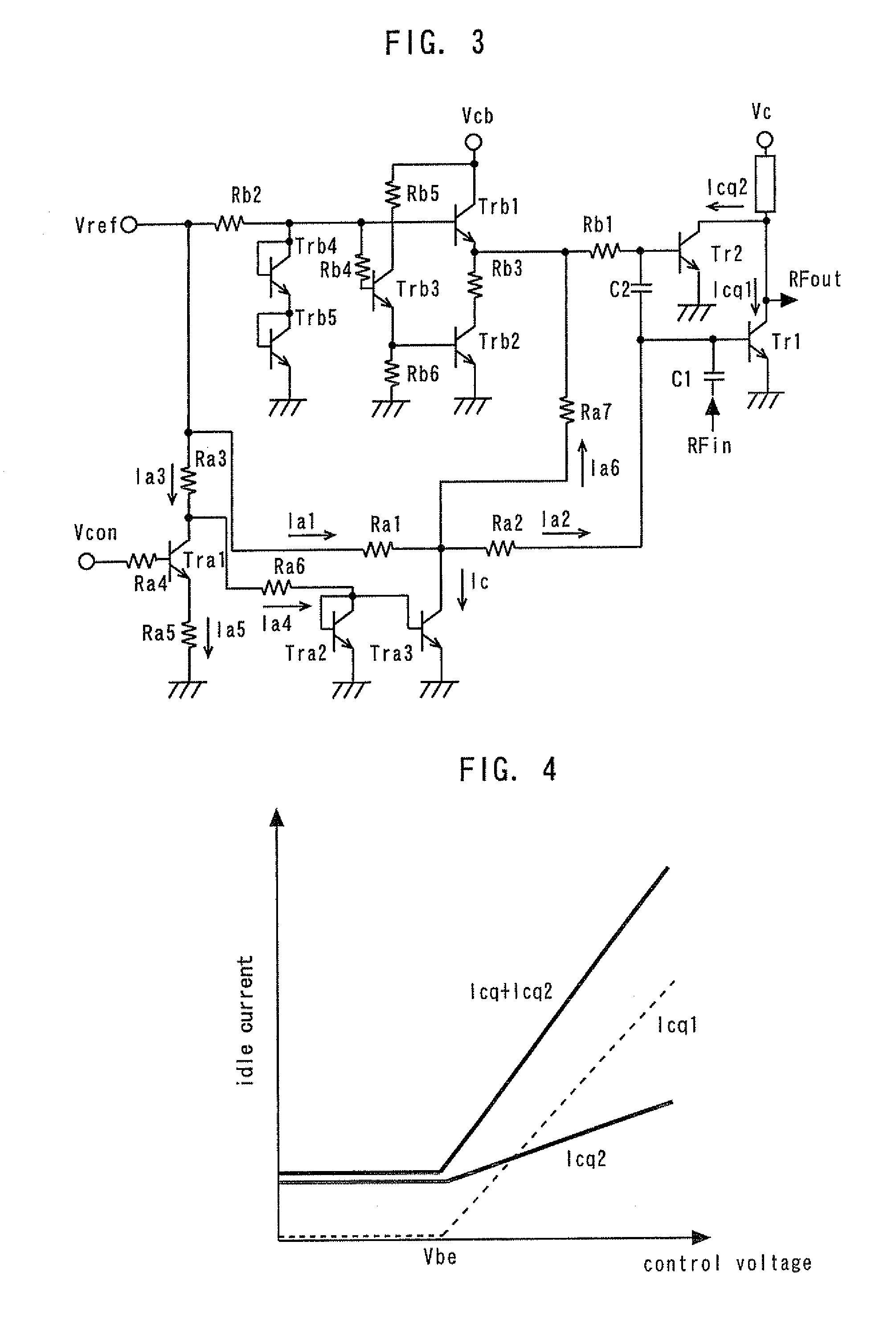
[0051]FIG. 3 is a circuit diagram showing a power amplifier according to a second embodiment of the present invention. A fourth resistor Ra7 is connected between the base (input terminal) of the second amplifying device Tr2 and the connection point between the first and second resistors Ra1 and Ra2. In other respects, the configuration of the second embodiment is the same as that of the first embodiment. This arrangement enables maintaining the control voltage and the idle current in a linear relationship with respect to the second amplifying device Tr2 as well as with respect to the first amplifying device Tr1, as shown in FIG. 4. Thus, the idle current through the second amplifying device Tr2 can be increased during high-output-power operation to obtain an output characteristic with reduced distortion.
third embodiment
[0052]FIG. 5 is a circuit diagram showing a power amplifier according to a third embodiment of the present invention. The base and the collector of the second transistor Tra4 are connected to the reference terminal Vref. A fifth resistor Ra8 is connected between the emitter of the second transistor Tra4 and the connection point between the first and second resistors Ra1 and Ra2. In other respects, the configuration of the third embodiment is the same as that of the first embodiment.
[0053]In the first embodiment, if the control voltage is constant, the idle current Icq1 through the first amplifying device Tr1 is constant with respect to varying temperature. If the idle current is constant, the gain of the HBT power amplifier decreases with increase in temperature. Thus, there has been a problem that the gain of the power amplifier decreases with increase in temperature. In the third embodiment of the present invention, the idle current Icq1 through the first amplifying device Tr1 can...
PUM
 Abstract
Description
Claims
Application Information
 - R&D
- Intellectual Property
- Life Sciences
- Materials
- Tech Scout
- Unparalleled Data Quality
- Higher Quality Content
- 60% Fewer Hallucinations
Browse by: Latest US Patents, China's latest patents, Technical Efficacy Thesaurus, Application Domain, Technology Topic, Popular Technical Reports.
© 2025 PatSnap. All rights reserved.Legal|Privacy policy|Modern Slavery Act Transparency Statement|Sitemap|About US| Contact US: help@patsnap.com


