Conductive hook and loop printed circuit board attachment

a technology of printed circuit board and hook and loop, which is applied in the direction of coupling device connection, sustainable manufacturing/processing, and final product manufacturing, etc. it can solve the problems of not appreciably increasing the cost of absorbent articles, material inability to satisfactorily attach devices to articles, and consumer electronics have spread into non-traditional product categories, etc. good electrical conductivity, high volume, and relatively cheap

Inactive Publication Date: 2009-04-28
KIMBERLY-CLARK WORLDWIDE INC
View PDF3 Cites 25 Cited by
  • Summary
  • Abstract
  • Description
  • Claims
  • Application Information

AI Technical Summary

Benefits of technology

[0008]The hook and loop attachments can be any conventional hook and loop attachment known in the art and, as such, can be produced relatively cheaply and in high volume. Furthermore, the attachment configurations disclosed in the present disclosure provide good electrical conductivity and a sufficiently secured mechanical attachment to a printed circuit board.
[0010]The present disclosure is further directed to a conductive connector attachment for a printed circuit board. The conductive connector attachment comprises a conductive hook material, a printed circuit board, and a conductive loop material. The conductive hook material comprises a contact side and an opposing non-contact side. The contact side comprises multiple hooks. The non-contact side comprises at least one stud. The printed circuit board comprises at least one via, wherein the stud of the conductive hook material is compatible with the via and can be fitted into the via, thereby electrically connecting the printed circuit board to the non-contact side of the conductive hook material. In one embodiment, a solder material can be applied to the stud material, allowing for an even stronger connection between the printed circuit board and the conductive hook material. Furthermore, the conductive loop material is compatible with the contact side of the conductive hook material and, as such, can be securely fastened thereto.

Problems solved by technology

Recently, however, consumer electronics have spread into non-traditional product categories such as consumer products and textiles.
Problems, however, have been encountered in designing an attachment mechanism for the signaling device that allows for a very reliable attachment of the signaling device to the conductive leads while not appreciably increasing the cost of the absorbent article.
Furthermore, while alternatives to metal connectors, such as conventional conductive plastics and conductive threads, are known, these materials have been unable to attach the devices to the articles satisfactorily.
Furthermore, the affinity of solder materials typically used in attaching these types of connectors to printed circuit boards is low and, as such, when attempting to directly solder a patch of a connector onto a printed circuit board, a cold solder joint is formed which results in the thermoplastic material of the connector cracking away from the solder material, producing an unsatisfactory bond.

Method used


Image

  • Conductive hook and loop printed circuit board attachment
  • Conductive hook and loop printed circuit board attachment
  • Conductive hook and loop printed circuit board attachment

Examples


example 1

[0061]In this Example, a conductive connector attachment was produced in accordance with one embodiment of the present disclosure and its connection resistance was compared to a control attachment sample.

[0062]To produce the conductive connector attachment, round holes (approximately 2 mm to 4 mm) were made into a conductive hook material (commercially available as conductive VELCRO from Velcro USA, Inc., Manchester, N.H.) using needle point. The conductive hook material was then adhered to a one-sixteenth inch thick metal plate using a conductive epoxy, available as a silver two-part epoxy (resin and hardener with suspended silver particles) from Chemtronics, Kennesaw, Ga. Specifically, the surface of the metal plate was roughed up using a steel brush. Then, a few grams of mixed epoxy were placed on an epoxy patch on the conductive hook material. Pressure was applied to allow for the epoxy to push through the holes. The metal plate was then allowed to stand for approximately two ho...

example 2

[0065]In this Example, samples of conductive hook materials were directly soldered to printed circuit boards using conventional soldering mechanisms. Specifically, the samples were produced by melting, at a temperature of approximately 315° C. to 371° C. (600-700° F.) using a Weller soldering iron, the thermoplastic material of the conductive hook materials (commercially available as conductive VELCRO from Velcro USA, Inc., Manchester, N.H.) into a solder material (commercially available as Kester 24-6337-8213 (a 63% tin / 37% lead alloy) from Digikey electronics, Thief River Falls, Minn.) and contacting the conductive hook materials to portions of the printed circuit boards (i.e., solder pads, each having a size of approximately 3 mm×7 mm) to create mechanical and electrical connections.

[0066]Connection resistance from the top of the hooks of the conductive hook material to the base of the printed circuit board of each sample was measured as in Example 1. Connection resistances were ...

example 3

[0067]In this Example, a sample of conductive connector attachment including metal throughholes in the conductive hook material was produced and its connection resistance was tested.

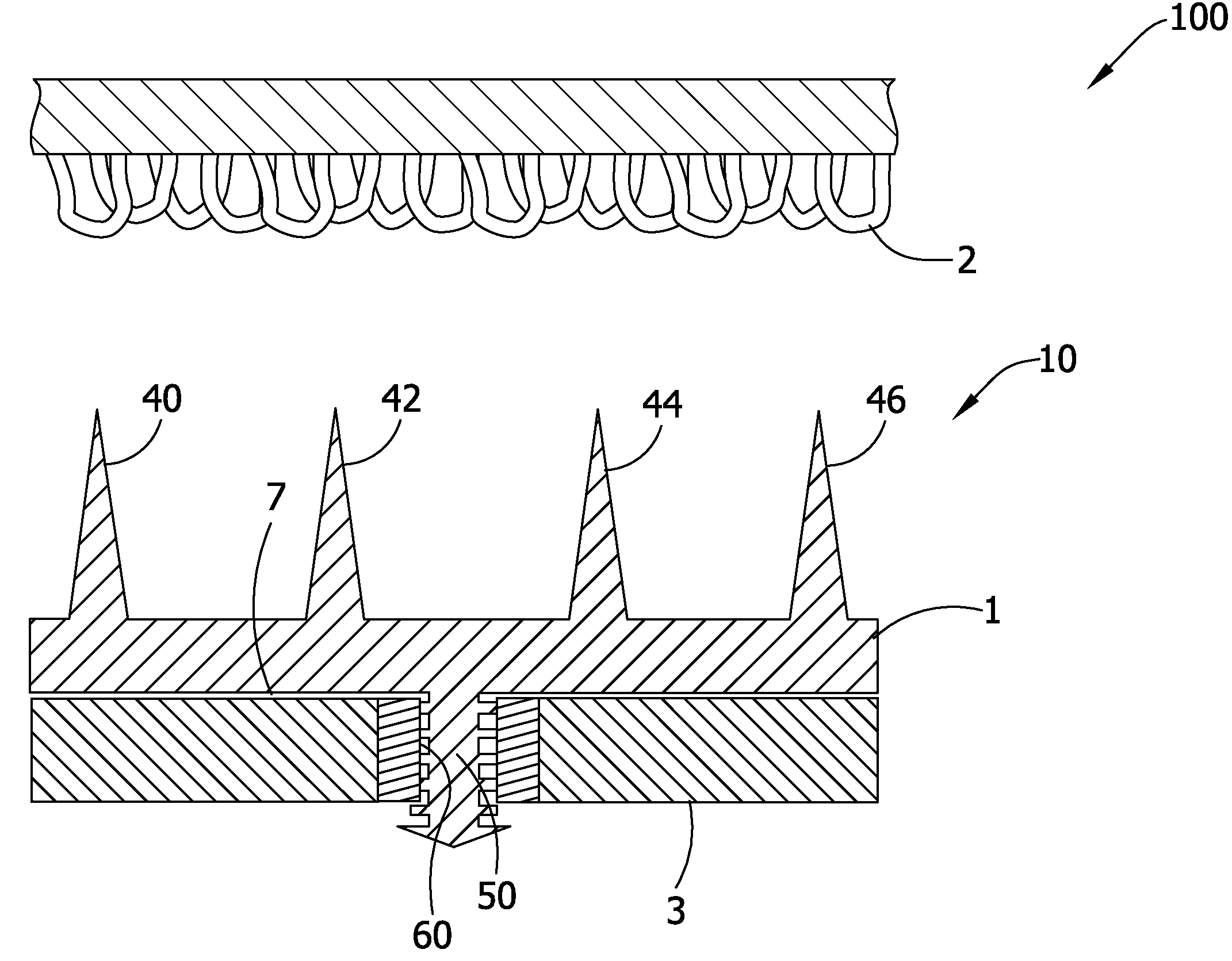
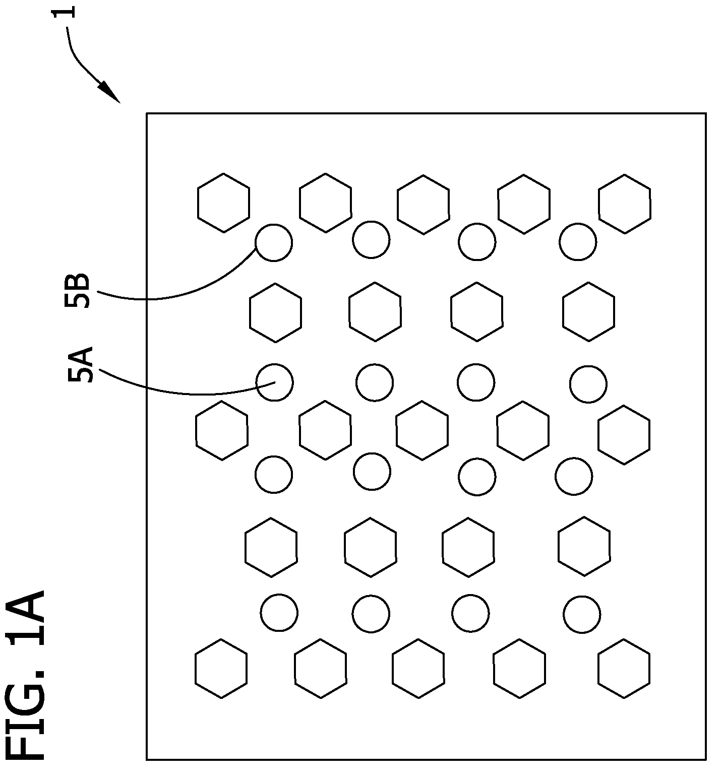
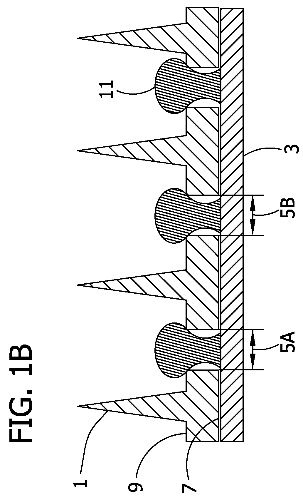
[0068]To produce the conductive connector attachment, the female portion of metal button snaps were placed through a conductive hook material (available as conductive VELCRO from Velcro USA, Inc., Manchester, N.H.) to produce a throughhole connection. The solder material, as used in Example 2, was applied to the snap throughhole and to a portion of a printed circuit board (i.e., solder pad, having a size of approximately 3 mm×7 mm). The snap throughhole connector of the conductive hook material was then soldered to the printed circuit board.

[0069]Connection resistance from one solder pad on the printed circuit board to one inch removed from the conductive hook material, taken through the snap throughhole of the conductive hook material, was measured as in Examples 1 and 2. Connection resistance was appro...


PUM


Abstract

The present disclosure is directed to conductive connector attachments for use in electrically connecting printed circuit boards to absorbent products such as diapers, training pants, incontinence products, feminine hygiene products, and the like. Specifically, various configurations and methods of securely attaching conventional conductive hook and loop attachments to printed circuit boards are disclosed.

Description

BACKGROUND OF DISCLOSURE[0001]The present disclosure generally relates to conductive connector attachments for printed circuit boards. More specifically, the present disclosure is directed to conductive hook and loop attachments for printed circuit boards.[0002]Current consumer electronic assembly is dominated with metal conduits and connections due to their high reliability, reasonable cost, and excellent electrical characteristics. Conventionally, printed circuit boards have been connected to integrated circuit semiconductor chips and the like using some type of intermediate device carrier. One such type of interconnection mounts the integrated circuit chip on a circuit chip carrier or module, which module in turn is mounted onto the circuit board. In a particularly well known type of interconnection mount, the integrated circuit chip is mounted onto a ceramic module by “flip-chip” bonding wherein the I / O pads on the face of the chip are bonded to corresponding pads on the module,...

Claims


Application Information

Patent Timeline
Patent Type & Authority Patents(United States)
IPC IPC(8): H01R12/00H01R12/50
CPCH01R13/03H01R43/0256H05K3/308H05K3/341H05K2201/1031H05K2201/209Y02P70/50
Inventor ALES, THOMAS MICHAELNHAN, DAVIS-DANG HOANG
Owner KIMBERLY-CLARK WORLDWIDE INC
Why Eureka
Try Eureka