Apex to aorta cannula assembly

a technology of aorta cannula and apex, which is applied in the field of medical devices, can solve the problems of chronic heart degradation, ultimate failure, and failure, and achieve the effect of reducing thrombosis

Active Publication Date: 2009-04-28
BOARD OF RGT THE UNIV OF TEXAS SYST
View PDF11 Cites 14 Cited by
  • Summary
  • Abstract
  • Description
  • Claims
  • Application Information

AI Technical Summary

Benefits of technology

[0011]The present invention provides an apparatus, system, and method for assisting a heart in circulating blood that has been damaged, for example, by a myocardial infarction. In at least one aspect, the invention provides an apparatus, system, and method for inserting a single cannula assembly comprising at least an inner and outer cannula into the left ventricle, advancing the inner cannula of the cannula assembly past the aortic valve, and int

Problems solved by technology

Often, the decay results in chronic heart degradation and ultimate failure, as the damaged portion is unable to be restored.
The damaged tissue, operating under high pressures, eventually fails.
Even without a failure, the heart is unable to function at a performance level prior to the MI, resulting in less circulation and lower blood oxygen levels.
Although cutting edge, critical care technology has been applied in the treatment and restoration of the cardiac tissues after an MI, the typical procedures are traumatic to many patients and sometimes result in mortality.
Less tissue decay can result from immediate and efficient cardiac or combined cardiac and pulmonary support, but the current technology is lacking in both aspects.
Current technology, including a left ventricle assist device (LVAD), extracorporeal membrane oxygenation (ECMO), and cardiopulmonary support (CPS), is either less efficient or too complicated and traumatic to already impaired anatomical systems.
The multiple insertions causes trauma, can result in bleeding especially by the return path to the arterial system, and the flow rates are limited by high resistance.
ECMO is also time limited, generally to less than four weeks, and has been shown

Method used


Image

  • Apex to aorta cannula assembly
  • Apex to aorta cannula assembly
  • Apex to aorta cannula assembly

Examples


Embodiment Construction

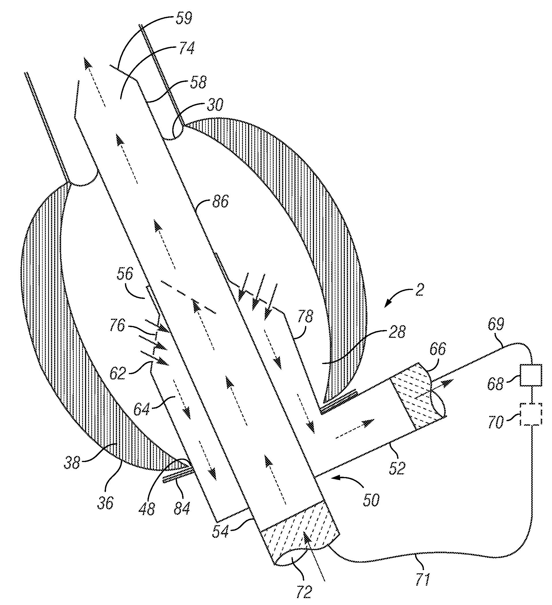
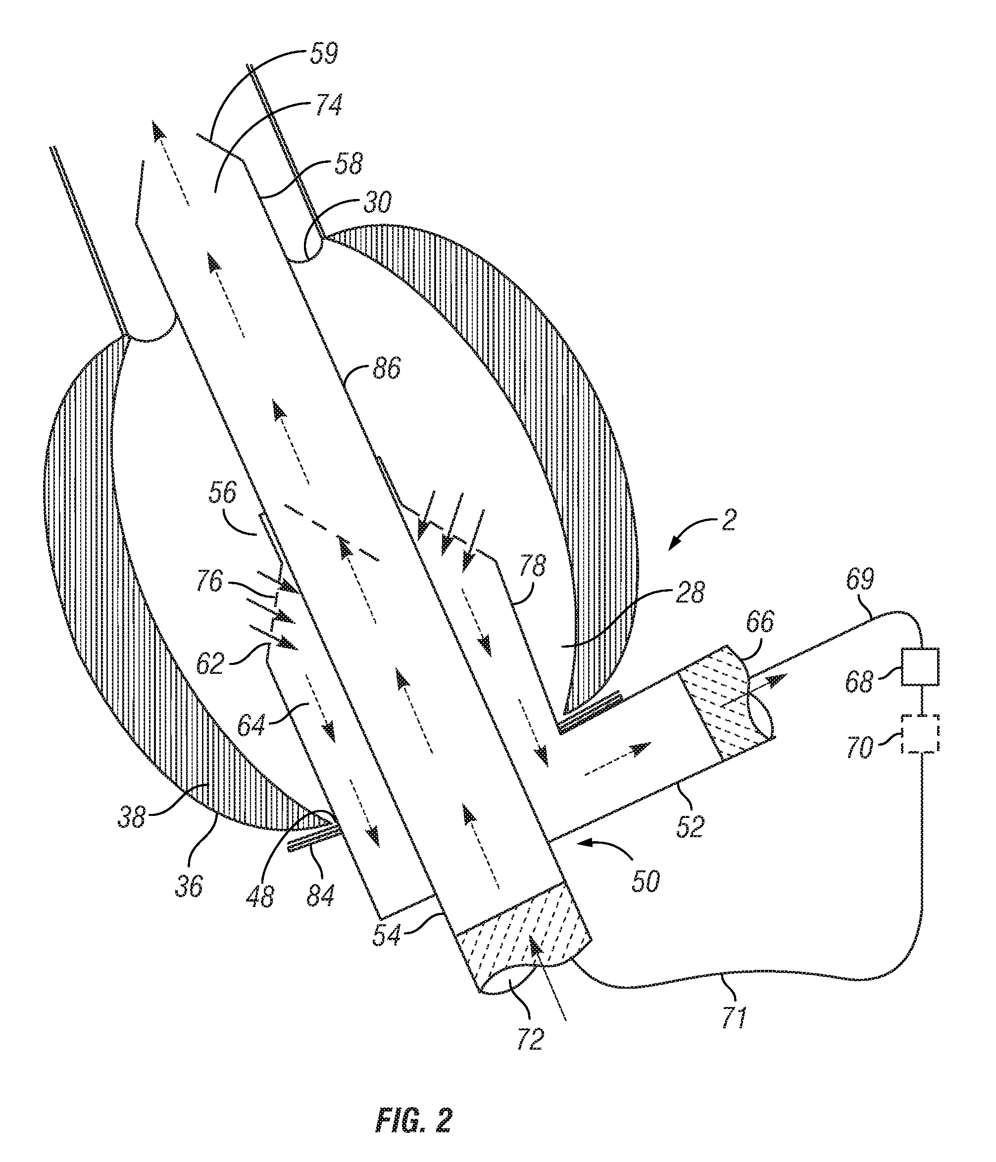
[0028]In general, the invention provides a cannula assembly having a double wall to create a readily installed, high-flow, low-resistant apex-to-aorta shunt that allows for rapid attachment to a blood-pumping device such as a ventricular assistant device, or a combination ventricular assistant device / oxygenator. The procedure for placement of the present invention cannula assembly is generally relatively simple, less time consuming, and less invasive than previous methods. In another aspect, the present invention provides a single lumen cannula with a built-in intraventricular pump that can be inserted at the apex of the heart and pumps blood from the left ventricle across the aortic valve to the ascending aorta.

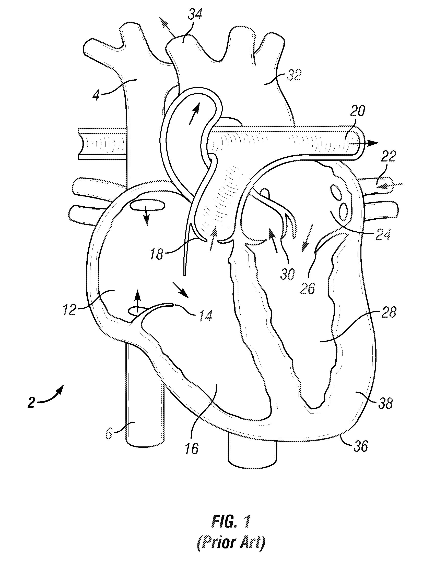
[0029]FIG. 1 is a diagram of a heart showing various portions relevant to the present invention. The following brief summary of the heart's circulatory system is included to provide a better understanding of the present invention. In general, a heart 2 receives blood from ve...


PUM


Abstract

An apparatus, system, and method for assisting a heart in circulating blood that has been damaged, for example, by a myocardial infarction. In at least one aspect, an apparatus, system, and method are used for inserting a single cannula assembly comprising at least an inner and outer cannula into the left ventricle, advancing the inner cannula portion of the cannula assembly past the aortic valve, and into the aorta without requiring a secondary cannula insertion through an external portion of the aorta. In another aspect, an intraventricular assistant device (IVAD) having a motor and impeller can be inserted directly into the heart, such as in the left ventricle. The IVAD uniquely provides a pump within the heart through a single insertion that can reduce thrombosis and lessen the complexities typically associated with such efforts.

Description

[0001]This application claims the benefit of U.S. Provisional Application Ser. No. 60 / 543,799, filed Feb. 11, 2004.FIELD OF THE INVENTION[0002]The invention relates to the field of medical devices. More specifically, the invention relates to the design and use of cardiac medical devices.BACKGROUND OF THE INVENTION[0003]Tissue decay in a heart typically results from a myocardial infarction (MI). Often, the decay results in chronic heart degradation and ultimate failure, as the damaged portion is unable to be restored. The deterioration is especially acute when the damage occurs to the left ventricle, which functions at a high pressure during systolic contractions to pump the blood received from the left atrium and the mitral valve, through the aortic valve and into the aorta for distribution throughout the body. The damaged tissue, operating under high pressures, eventually fails. Even without a failure, the heart is unable to function at a performance level prior to the MI, resultin...

Claims


Application Information

Patent Timeline
IPC IPC(8): A61M1/10A61M60/113A61M60/178A61M60/216A61M60/38A61M60/857A61M60/861A61M60/886
CPCA61M1/3653A61M1/3659A61M1/101A61M1/1698A61M1/3655A61M60/113A61M60/38A61M60/857A61M60/886A61M60/178A61M60/216A61M60/861
Inventor WANG, DONGFANGZWISCHENBERGER, JOSEPH B.
Owner BOARD OF RGT THE UNIV OF TEXAS SYST
Why Eureka
Try Eureka