
Nuclear spin polarized rare gas production device and polarized rare gas production method using this

a technology of rare gas and production device, which is applied in the direction of magnetic variable regulation, instruments, applications, etc., can solve the problems of reducing the polarization rate in the mean time, achieving the high polarization rate of rare gas, and reducing the entire excitation efficiency, so as to improve the vapor pressure of alkali metal and improve the vapor pressure

Inactive Publication Date: 2009-06-02
NAT INST OF ADVANCED IND SCI & TECH +1
View PDF7 Cites 4 Cited by
  • Summary
  • Abstract
  • Description
  • Claims
  • Application Information

AI Technical Summary

Benefits of technology

This approach significantly improves polarization rates, enabling continuous generation and shortens measurement times for NMR and MRI, enhancing detection sensitivity and miniaturizing detection areas without reducing polarization rates during transportation.

Problems solved by technology

An important technical problem exists in that rare gas having high polarization rate is achieved by a conventional NMR device.
But, the decrease in the polarization rate causes the decrease in the entire excitation efficiency.
A problem exists in that in a conventional device which stays gas or the like, and in which the gas is polarized, the polarized rare gas can not be continuously generated, and time is required for taking out the polarized gas to another container separately and carrying to the NMR device or the like, and the polarization rate is decreased in the mean time.
On the other hand, in a device which produces the polarized rare gas while making the gas flow, the following problems exists.
Since the buffer gas of the high pressure is introduced so as to reduce the los of the polarization rate due to the intermolecular collision of the polarized xenon-129, there is a danger of handling a gas.
Thereby a problem exists in that the polarization rate is decreased in a part away from the light source.

Method used


Image

  • Nuclear spin polarized rare gas production device and polarized rare gas production method using this
  • Nuclear spin polarized rare gas production device and polarized rare gas production method using this
  • Nuclear spin polarized rare gas production device and polarized rare gas production method using this

Examples


example

[0063]Then, example is shown below, and the invention of the application will be described. Of course, the invention is not limited to the following example.

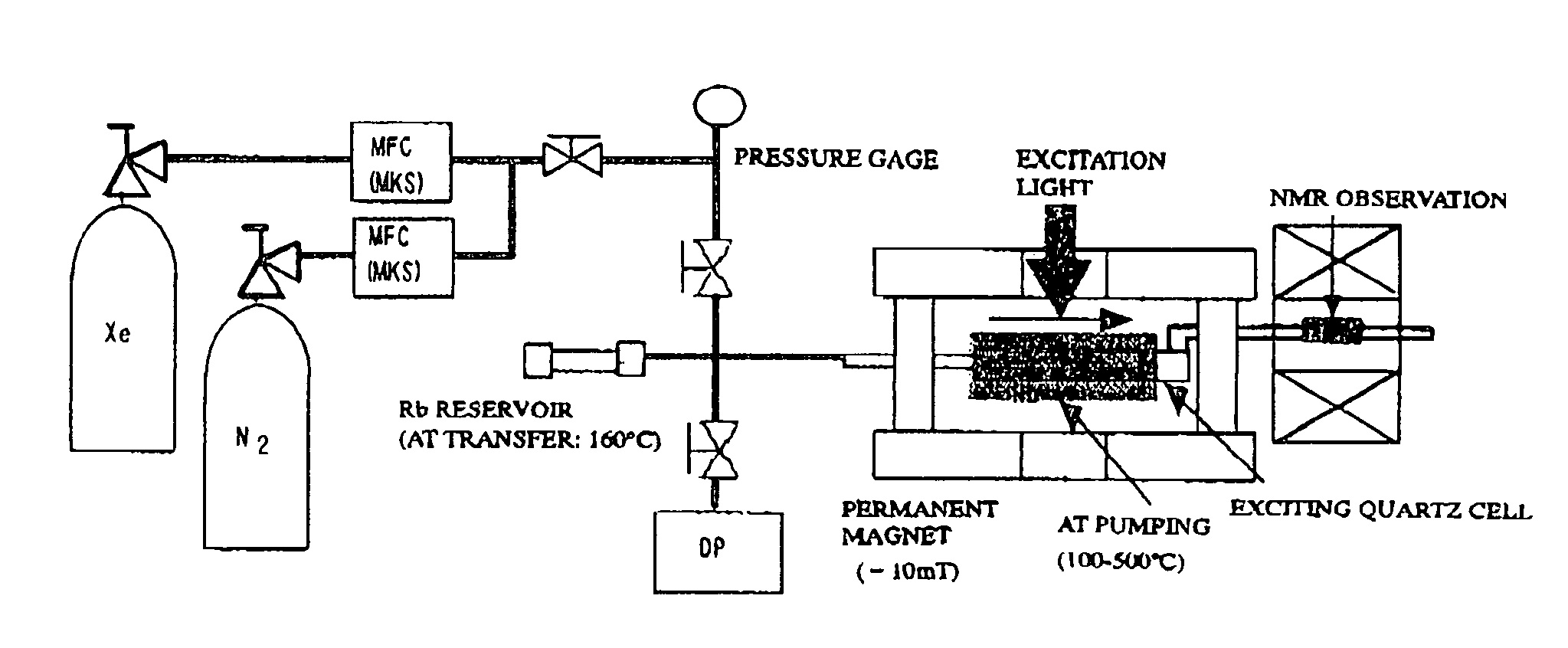
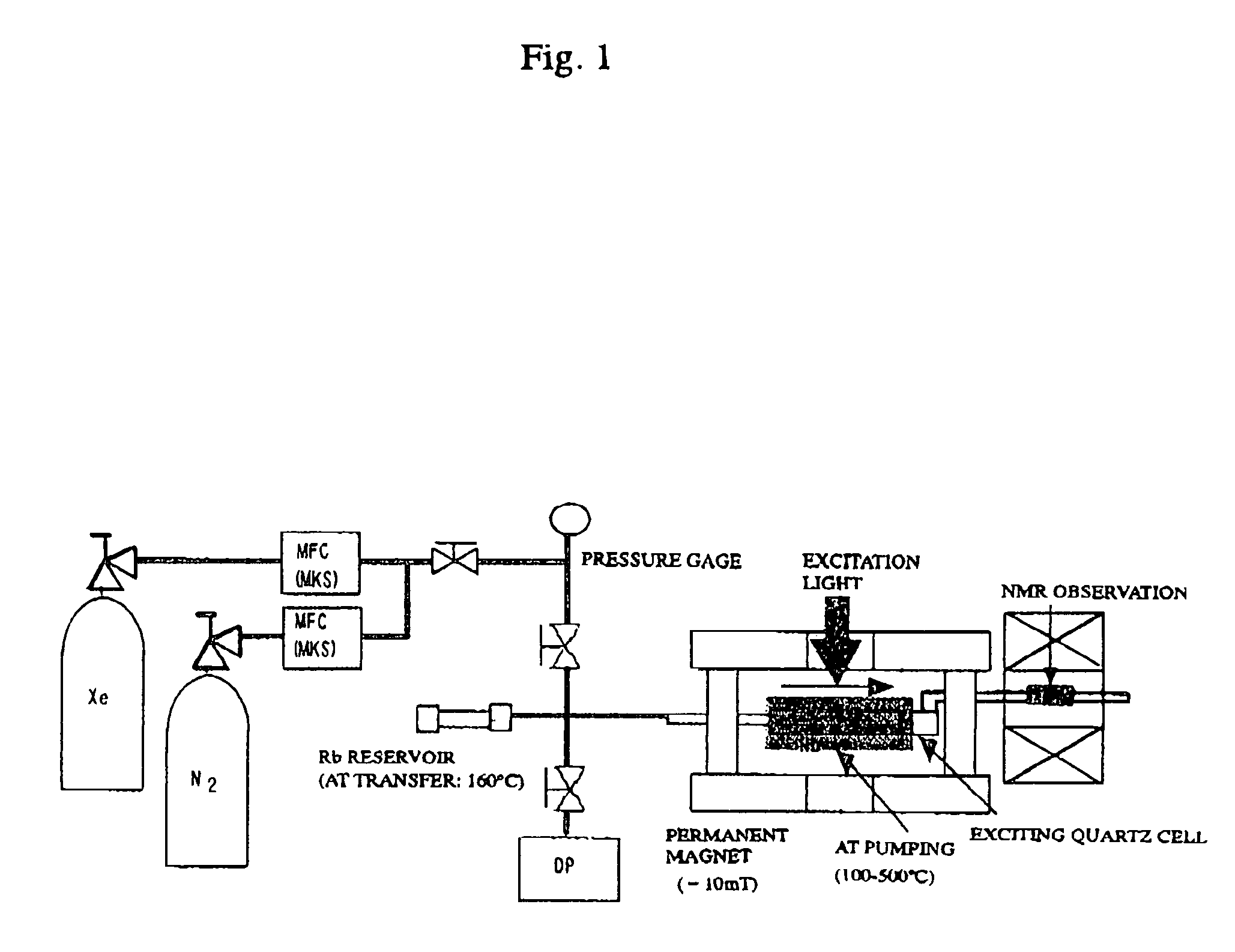
[0064]In the example, the device illustrated in FIG. 1 is used.

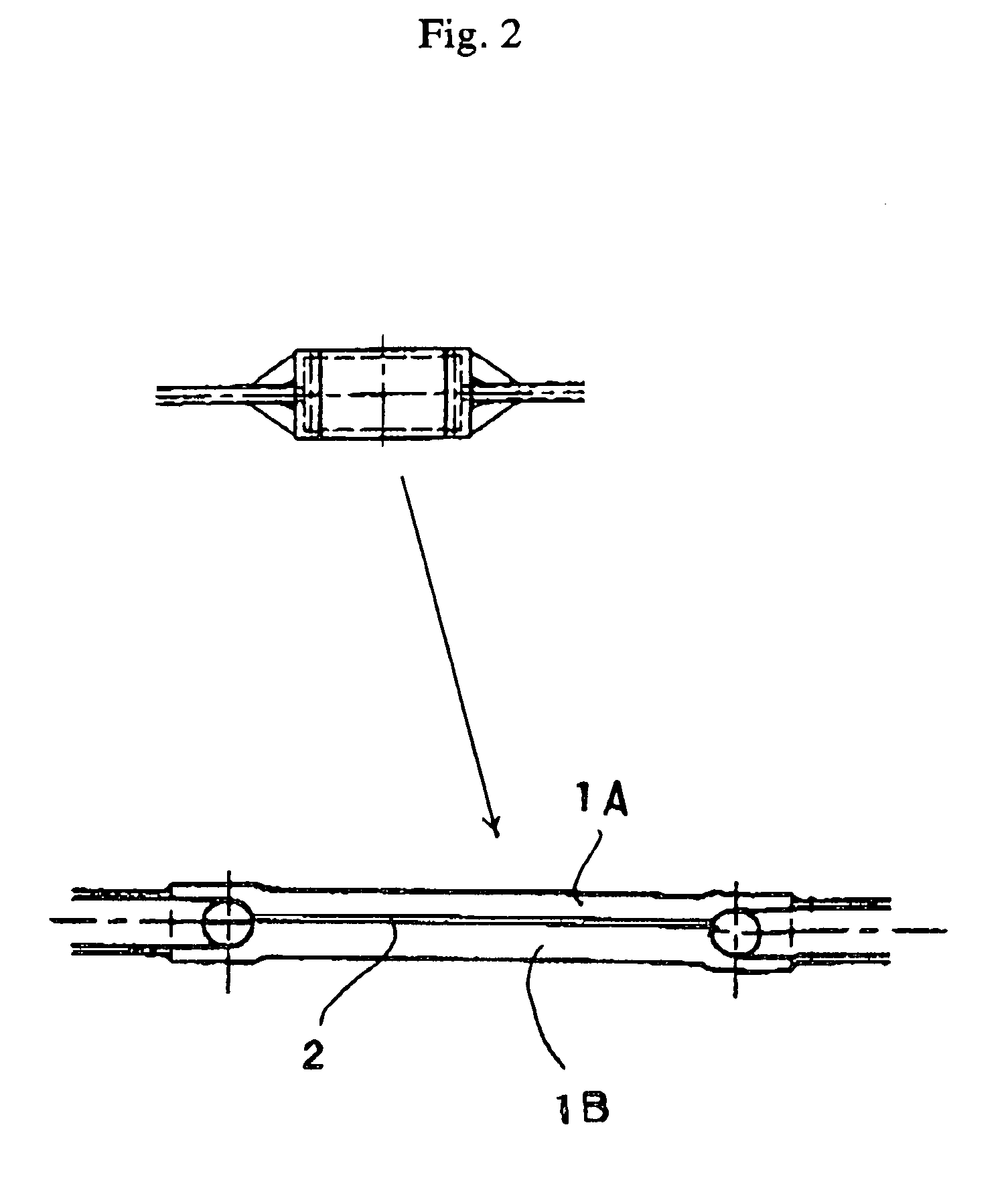
[0065]Xenon (purity: 99.95%) of a natural isotopic ratio manufactured by Nippon Sanso (xenon-129:26.44% content) is used for the rare gas, and nitrogen gas of S grade (purity: 99.9999%) manufactured by Nippon Sanso is used for the nitrogen gas. Each flow rate is controlled by a valve and mass flow controllers (trade name: M-100-11C, M-310-01C, manufactured by MKS Corporation). The gases are then mixed in a line, and are introduced into a flat-surface flow cell unit placed in a permanent magnet having an air core structure. At this time, the cell is controlled at the temperatures of about 150 to about 300° C. by a hot wind blowing heating device. In the flat-surface flow cell unit, rubidium (Rb) may be previously deposited as described in FIG. 3. When both the rubidiu...


PUM

PropertyMeasurementUnit
temperaturesaaaaaaaaaa
temperatureaaaaaaaaaa

Abstract

A device which can produce polarized rare gas further improved in polarization rate with the gas kept flowing, which has flat sheet surfaces facing each other via a gap, and which comprises, a flat-surface flow cell unit for allowing a mixture gas of rare gas and optically-pumping catalyst to flow in the gap there through in one direction thereof, a laser beam irradiation unit for applying a laser beam toward at least one of the flat sheet surfaces to apply an excitation light into the flat-surface flow cell unit, and a magnetic field application unit for allowing a magnetic line of force to pass through the laser beam-applied flat sheet surface perpendicularly or almost perpendicularly; and a method using this device.

Description

[0001]This application is a U.S. national stage of International Application No. PCT / JP03 / 01647 filed Feb. 17, 2003.TECHNICAL FIELD[0002]The invention of the application relates to a device for producing rare gas having high nuclear spin polarization rate, and a polarized rare gas production method using this. More particularly, the invention of the application relates to a device for producing rare gas polarized at the high rate of about several dozen percent or more, which is useful for a NMR device, and a polarized rare gas production method using this.BACKGROUND ART[0003]An important technical problem exists in that rare gas having high polarization rate is achieved by a conventional NMR device.[0004]Herein, the polarization means that the distribution of the number of spins occupying an energy level of a nuclear spin of the atomic nucleus corresponding to the state for the distribution to a main static magnetic field is extremely biased in comparison with the distribution at th...

Claims


Application Information

Patent Timeline
Patent Type & Authority Patents(United States)
IPC IPC(8): G01R33/28A61B5/055C01B23/00G01R33/26H01S3/00
CPCG01R33/282
Inventor HATTORI, MINEYUKIHIRAGA, TAKASHIMURAYAMA, MORIO
Owner NAT INST OF ADVANCED IND SCI & TECH
Learn More