Optical flame detection system and method

a flame detection and optical technology, applied in the field of flame detection, can solve the problems of loss of total value, destruction of indeterminate wildlife, millions of acres of forest and forest products, and destruction of the entire economy, and achieve good reflectivity

Active Publication Date: 2009-06-02
UNIVERSITY OF ALABAMA
View PDF43 Cites 55 Cited by
  • Summary
  • Abstract
  • Description
  • Claims
  • Application Information

AI Technical Summary

Benefits of technology

[0008]In one embodiment, a coating of nickel phosphorous with the phosphorous at or above 20 atomic percentile has been found to have a good reflectivity at UVC.
[0010]The dramatically improved performance of the detector over present commercially available units can provide for enhanced response time for the responsible fire fighting agencies to protect homes, industries, forest resources and other jeopardized entities. The addition of a transmitter or transponder augments the remote sensing system.

Problems solved by technology

The United States presently ranks seventh in total acreage lost but much worse in total value lost from open area fires.
It is well known that open area fires destroy indeterminate wildlife, millions of acres of forest and forest products as well as creating about ⅓ of the pollution particulates and CO2 in the US alone.
Worldwide wildfires are devastating the entire economy in many countries.
Such is the case in Indonesia, North African countries and other countries without sufficient resources to extinguish large fires.
Indonesia has lost as much as 50% of the useful forest products in many areas to fires in recent years.
Flame and smoke detectors are marketed by as many as 60 companies in the US but have not found widespread use in the detection of forest and open area fires due to the limited range of detection and the lack of reporting systems.

Method used


Image

  • Optical flame detection system and method
  • Optical flame detection system and method
  • Optical flame detection system and method

Examples


examples

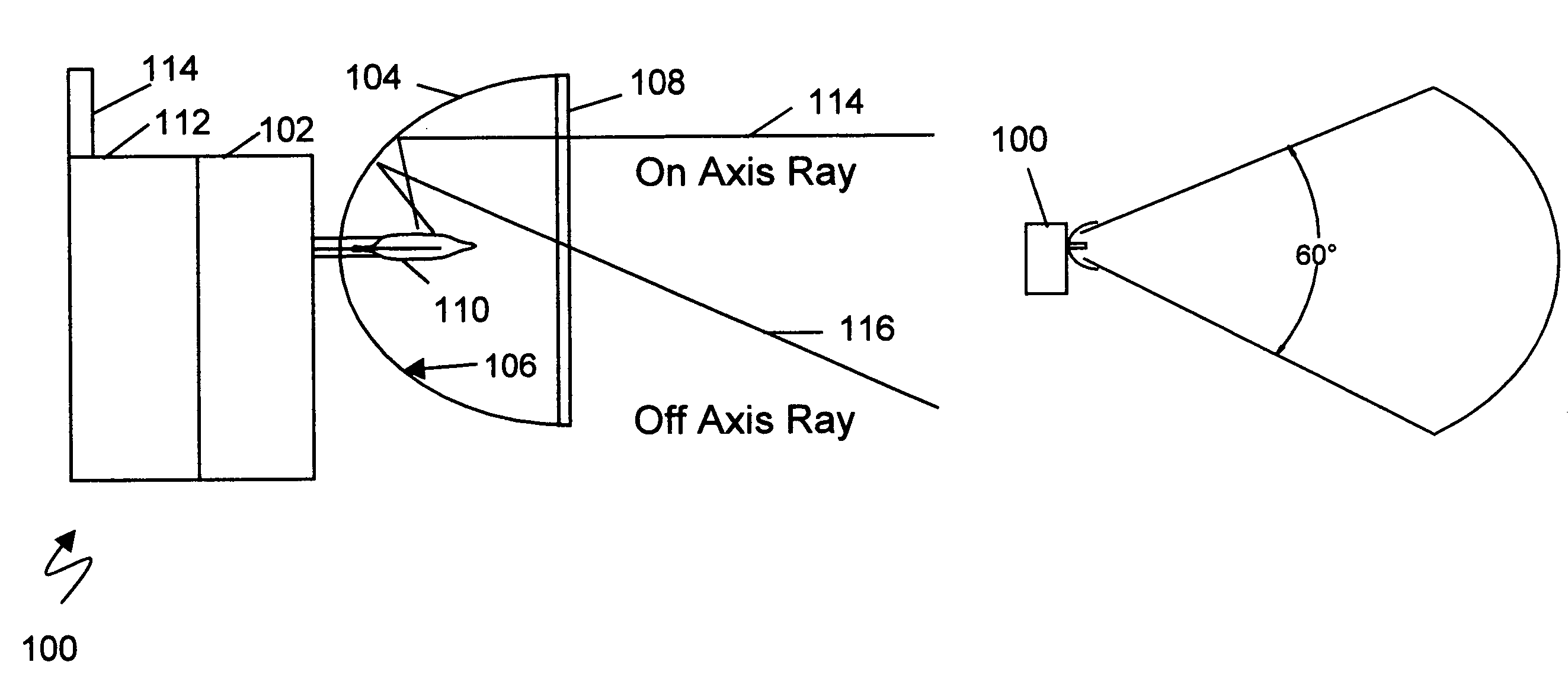
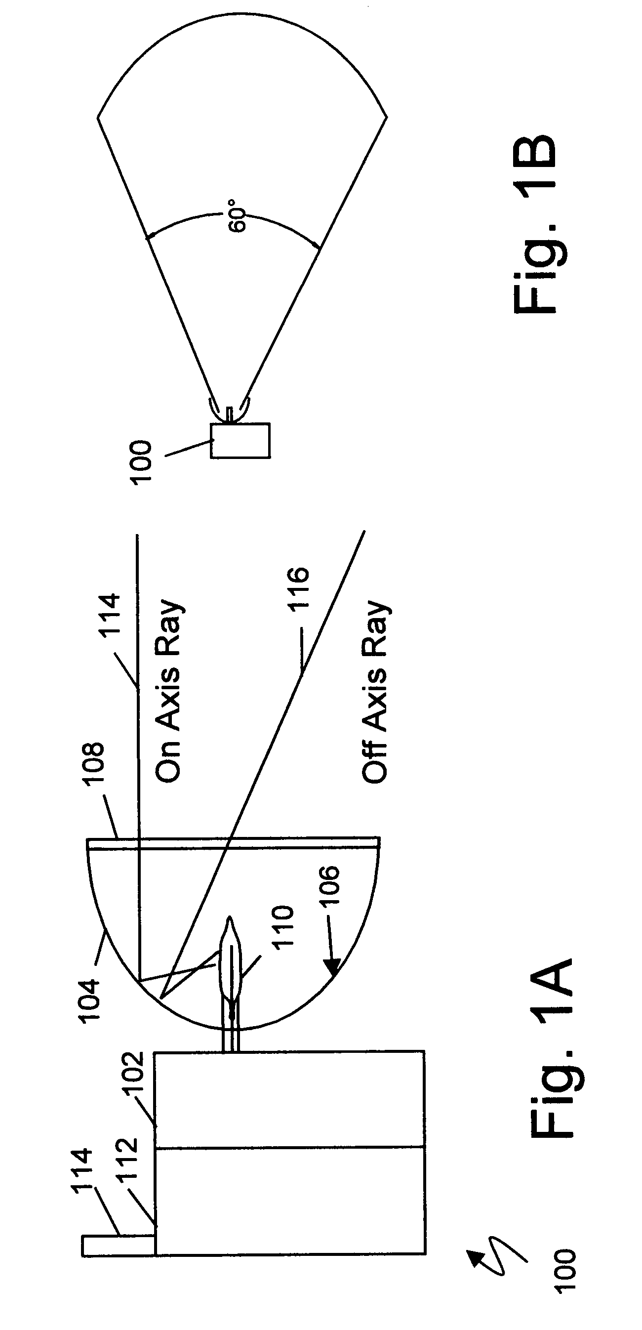
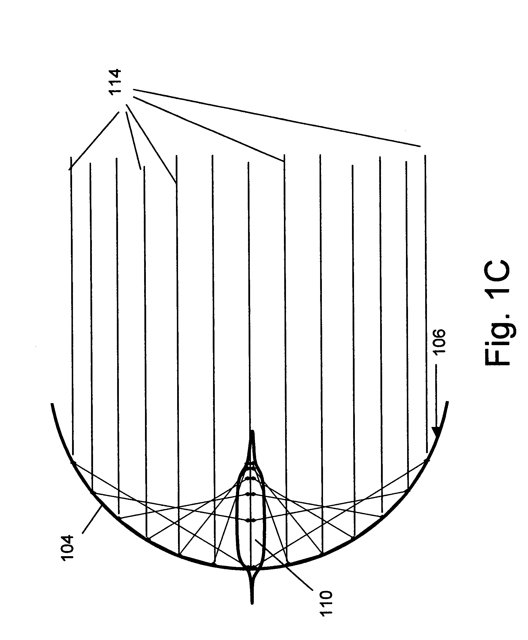
[0041]Demonstration by way of the following examples has been accomplished.[0042]1.0 A commercial Geiger Mueller “UV TRON” detector from Hamamatsu, Inc. was tested in accordance to the advertised specifications. The performance of the UV TRON was measured prior to adding the collector and found to be better than the advertised specification of 5 meters with detection of a one cm^2 flame (kitchen match) with a 90 degree FOV at about 7-8 meters. This same detector was tested in an environment of intense UVA mercury vapor lights and did not respond to the lighting. Likewise it was tested in bright sunlight directing the detector to the sun. Again it did not respond without the flame. It performed as advertised. The same detector was then configured with an electroformed collector with first surface of 20% phosphorus and balance nickel. The collector was placed with the GM tube axially aligned such that the mid-point of the GM tube was at the spherical focal point. The diameter of the s...


PUM


Abstract

A long range optical sensor and system for detecting the flame of forest fires or other fires while rejecting false alarms due to solar radiation is described. The sensor utilizes a collector optic that collects energy from a wide field of view and concentrates the energy onto a detector. The collector may be a non-imaging collector and may match to a non-planar sensor. In one embodiment the sensor may be arrayed to achieve larger area coverage. In another, the sensor system may be scanned to increase the encompassed viewing area. Larger areas may be covered by RF radio links or networks interconnecting multiple arrayed sensor modules. UVC reflective coatings may include enhanced aluminum with silicon dioxide, silicon monoxide, or magnesium fluoride, or high phosphorous nickel phosphorous. In one embodiment a UVC sensitive Geiger Mueller tube may be coupled to a non-imaging spherical reflective collector. A catadioptric UVC / infra-red flame sensor is disclosed. Refractive or reflective designs are considered.

Description

RELATED APPLICATIONS[0001]This application claims the benefit under 35 USC 119(e) of prior provisional application 60 / 787,032, titled “Multispectral Flame Detection and Reporting”, filed Mar. 29, 2006 by Darell E. Engelhaupt, which is incorporated herein by reference in its entirety.[0002]Other US patent documents referenced herein are incorporated herein by reference.BACKGROUND[0003]1. Field of the Invention[0004]The present invention pertains generally to the field of flame detection, more particularly to the field of flame detection by specifically enhanced optical means to provide for more rapid and accurate reporting of distant or remote fires. The use of RF transmitters is described also permitting a robust long range sensing system to be constructed economically.[0005]2. Background of the Invention[0006]Recent annual United States Federal expenditures for forest and other open area fire protection is about $4.7 billion dollars and about an equal amount is provided by state an...

Claims


Application Information

Patent Timeline
Patent Type & Authority Patents(United States)
IPC IPC(8): G08B17/12
CPCG08B17/12
Inventor ENGELHAUPT, DARELL EUGENE
Owner UNIVERSITY OF ALABAMA
Why Eureka
Try Eureka