Multifunction receiver-on-chip for electronic warfare applications

a receiver and multi-functional technology, applied in the field of receivers, can solve the problems of excessive power consumption, excessive power consumption, and high cost of the driver of such a modular system, and achieve the effects of optimizing the duration, reducing the cost of operation, and increasing flexibility

Inactive Publication Date: 2009-06-02
BAE SYST INFORMATION & ELECTRONICS SYST INTERGRATION INC
View PDF5 Cites 32 Cited by
  • Summary
  • Abstract
  • Description
  • Claims
  • Application Information

AI Technical Summary

Benefits of technology

[0011]Rather than using either the MCM approach or any other modular approach, assuming for instance 5 modules, each six inches square, by using system-on-a-chip (SOC) architecture and the new IBM silicon-germanium transistor technology with switch speeds in excess of 100 GHz one can reduce the entire EW receiver to a package the size of 3 inches by 2 inches.
[0012]Moreover, since the interconnections between the various circuits that are monolithically formed on the chip are on the order of microns in length rather than wires of an inch or more, transmission line losses are eliminated along with the weight associated with the coaxial cable interconnects. Not only is the physical size reduced by an order of magnitude, but also because of the monolithic integrated approach, one completely eliminates the I / O buffers between the circuits, which significantly reduces the power consumption.
[0013]Even more significant is the fact that having achieved a receiver-on-a-chip package size of 2 inches by 3 inches, each receiver in and of itself can be placed adjacent an antenna element, with downstream communication being accomplished through fiber optic cables such that weight concerns, losses and impedance mismatches associated with coaxial cabling between the antenna elements and the processors are completely eliminated.

Problems solved by technology

These modules include low noise amplifiers, analog-to-digital converters, filters, mixers, IF stages, amplifiers and processors that constitute a centralized receiver system that is complex, heavy, consumes an excessive amount of power and is expensive.
In addition to weighing in excess of 60 pounds, the input / output (I / O) drivers of such a modular system can consume as much as 15 watts of power out of a 25-watt total, with the power drain primarily residing in the interfaces between the modules.
This is because the interfaces must employ drivers that consume an excessive amount of power.
Moreover, cabling between the modules and to antenna elements is heavy and leads to cable losses that result in power drain and decreased receiver sensitivity.
When the UAVs hover over an area sometimes for days, weeks or months, the longevity of the mission is critically dependent upon fuel consumption, which is in turn directly related to power consumption of the avionics package.
Size reduction is also a factor because present rack-mounted modular EW systems occupy too much space to be incorporated into the UAV avionics package.
It will thus be appreciated that in high-altitude, long-endurance UAVs the physical size of the avionics package is a problem.
While one might be inclined to produce an EW receiver using multi-chip modules or MCM technology, it will be appreciated that the multi-chip module approach also consumes a significant amount of power.
While the multi-chip module can shrink the size of the system to a certain extent, one must address the I / O interface power requirements, which as mentioned above can result in 15 watts wasted power out of the 25-watt total requirement.
This power consumption is added to a 2-watt current consumption for the I / O to the CMOS digital DSP.
While power consumption of a modular receiver utilizing MCM technology is indeed a problem, there is also a requirement to improve on all of the characteristics of an MCM system to not only decrease power consumption for increasing endurance, but also to increase the dynamic range, provide improved instantaneous bandwidth, increase the operating frequency bandwidth beyond the usual 2 GHz to 18 GHz bandwidth, and increase the mean time before failure (MTFB).

Method used


Image

  • Multifunction receiver-on-chip for electronic warfare applications
  • Multifunction receiver-on-chip for electronic warfare applications
  • Multifunction receiver-on-chip for electronic warfare applications

Examples


Embodiment Construction

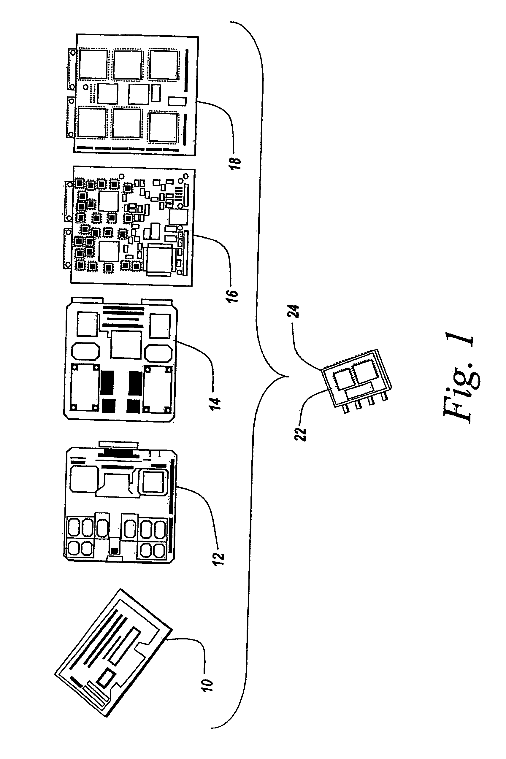
[0044]Referring to FIG. 1, current modular digital EW receivers have a number of modules 10, 12, 14, 16 and 18, respectively an RF converter module, a module for the first half of an IF conversion section, a second module of an IF conversion section, an RF digitizer module, and an RF digital processing module. These modules are cabled together in an electronics suite within an aircraft so as to provide the requisite digital receiver functions for surveillance, intelligence gathering and oftentimes for direction finding and fire control. Typically, each of these modules is 6 inches on a side so as to comprise at least 30 inches of rack space within the electronics suite of the aircraft.

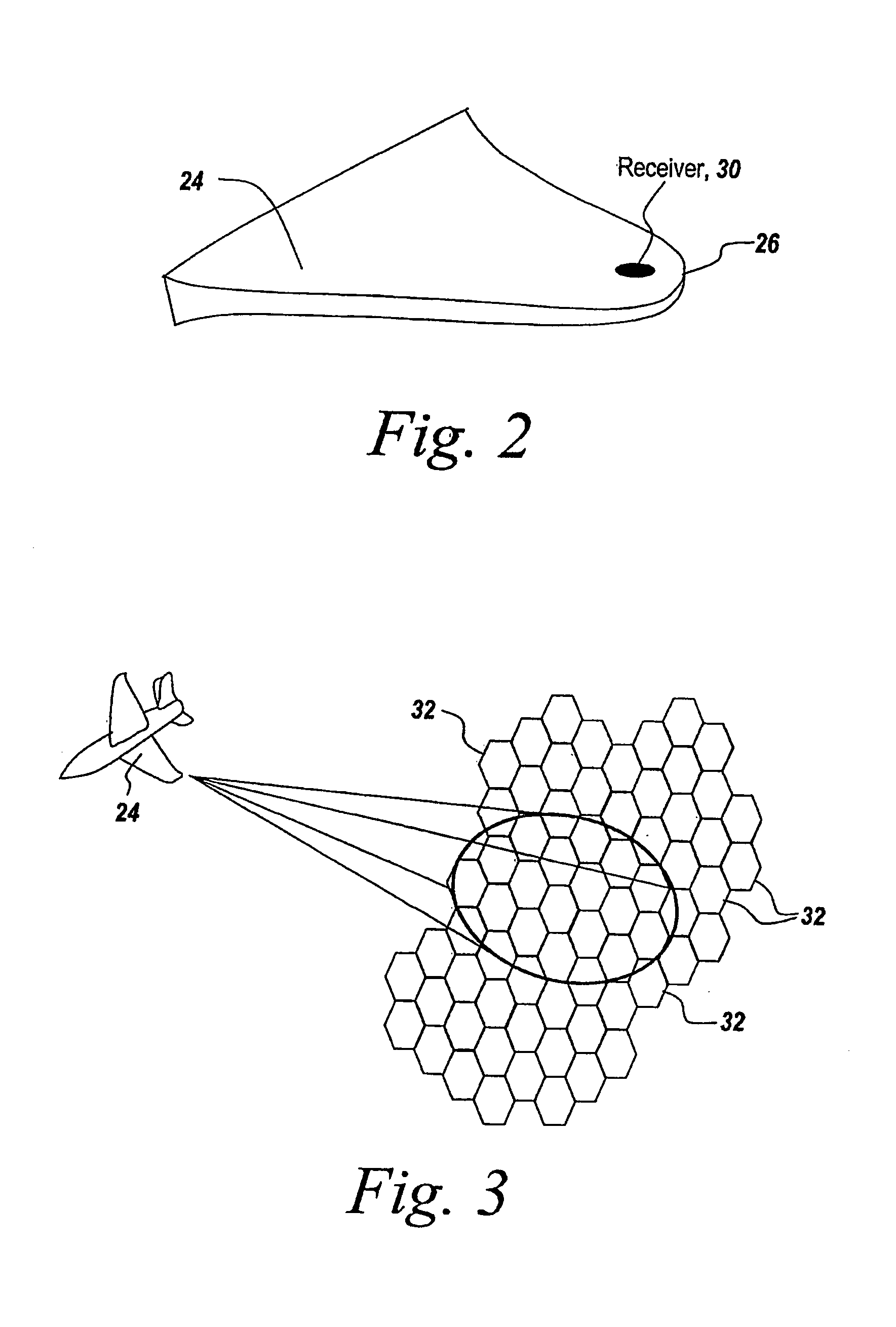
[0045]As mentioned hereinbefore, these modules are usually interconnected by coaxial cables as well as being connected by coaxial cable to various antenna elements in the antenna array, usually embedded in the wing 20 of an aircraft 21.

[0046]As mentioned hereinbefore, the weight, power consumption, los...


PUM


Abstract

What is provided is a receiver-on-a-chip comprising a monolithic integrated circuit that reduces the receiver to a cigarette-pack-sized assembly mountable directly at an antenna element, with a much-increased operational bandwidth and instantaneous bandwidth, increased dynamic range and with a two-order-of-magnitude decrease in size and weight. Moreover, because of the elimination of all of the I / O drivers and attendant circuitry, power consumption is reduced by two-thirds, whereas the mean time before failure is increased to 10,000 hours due to the robustness of the monolithic integrated circuit and use of fiber optics.

Description

RELATED APPLICATIONS[0001]This Application claims rights under 35 USC § 119(e) from U.S. Application Serial No. 60 / 537,867 filed Jan. 20, 2004, the contents of which are incorporated herein by reference.STATEMENT OF GOVERNMENT INTEREST[0002]The invention was made with United States Government support under Contract No. DAAB07-02-C-K513 awarded by the Army. The United States Government has certain rights in this invention.FIELD OF THE INVENTION[0003]This invention relates to receivers used in electronic warfare and more particularly to a miniaturized receiver-on-a-chip, placeable directly at an antenna element in which prior electronic warfare, EW, receiver modules are integrated monolithically into a single integrated circuit using ultra high-speed transistors.BACKGROUND OF THE INVENTION[0004]For many electronic warfare applications, phased array antennas are used for beam forming or direction finding purposes in which an aircraft, for instance, is provided with an antenna array, th...

Claims


Application Information

Patent Timeline
Patent Type & Authority Patents(United States)
IPC IPC(8): G01S7/42
CPCG01S7/032G01S7/38
Inventor STROILI, FRANK D.HUGGETT, JAMES M.
Owner BAE SYST INFORMATION & ELECTRONICS SYST INTERGRATION INC
Why Eureka
Try Eureka