MRI apparatus and ASL imaging technique

a magnetic resonance imaging and asl imaging technology, applied in the field of magnetic resonance imaging apparatus and asl imaging technique, can solve the problems of unsolved problems, blood flow cannot reach the imaging region of interest within the ti time, under evaluation, etc., and achieve the effect of reducing td time-induced errors and increasing sensitivity

Active Publication Date: 2009-06-09
TOSHIBA MEDICAL SYST CORP
View PDF10 Cites 25 Cited by
  • Summary
  • Abstract
  • Description
  • Claims
  • Application Information

AI Technical Summary

Benefits of technology

[0021]The invention was devised in view of the problems of the UVS-ASL technique (the VS-ASL technique of the unipolar-VENC type) described above, and a first object of the invention is therefore to provide ASL

Problems solved by technology

However, in cases like the cerebral infarction where the blood flow velocity is reduced or where the Td time is extended due to a collateral vessel, the blood flow cannot reach the region of interest in the imaging region within the TI time, 1 to 2 sec. after the labeling.
The flow is thus often under evaluated, which is reported as an issue of concern.
The UVS-ASL technique, however, has unsolved problems as follows.
(1) A first unsolved problem is low sensitivity.
To be more specific, in the UVS-ASL technique, there occurs unbalanced spoiling of the

Method used


Image

  • MRI apparatus and ASL imaging technique
  • MRI apparatus and ASL imaging technique
  • MRI apparatus and ASL imaging technique

Examples


first embodiment

[0057]A first embodiment of the invention will be described with reference to FIG. 3 through FIG. 12.

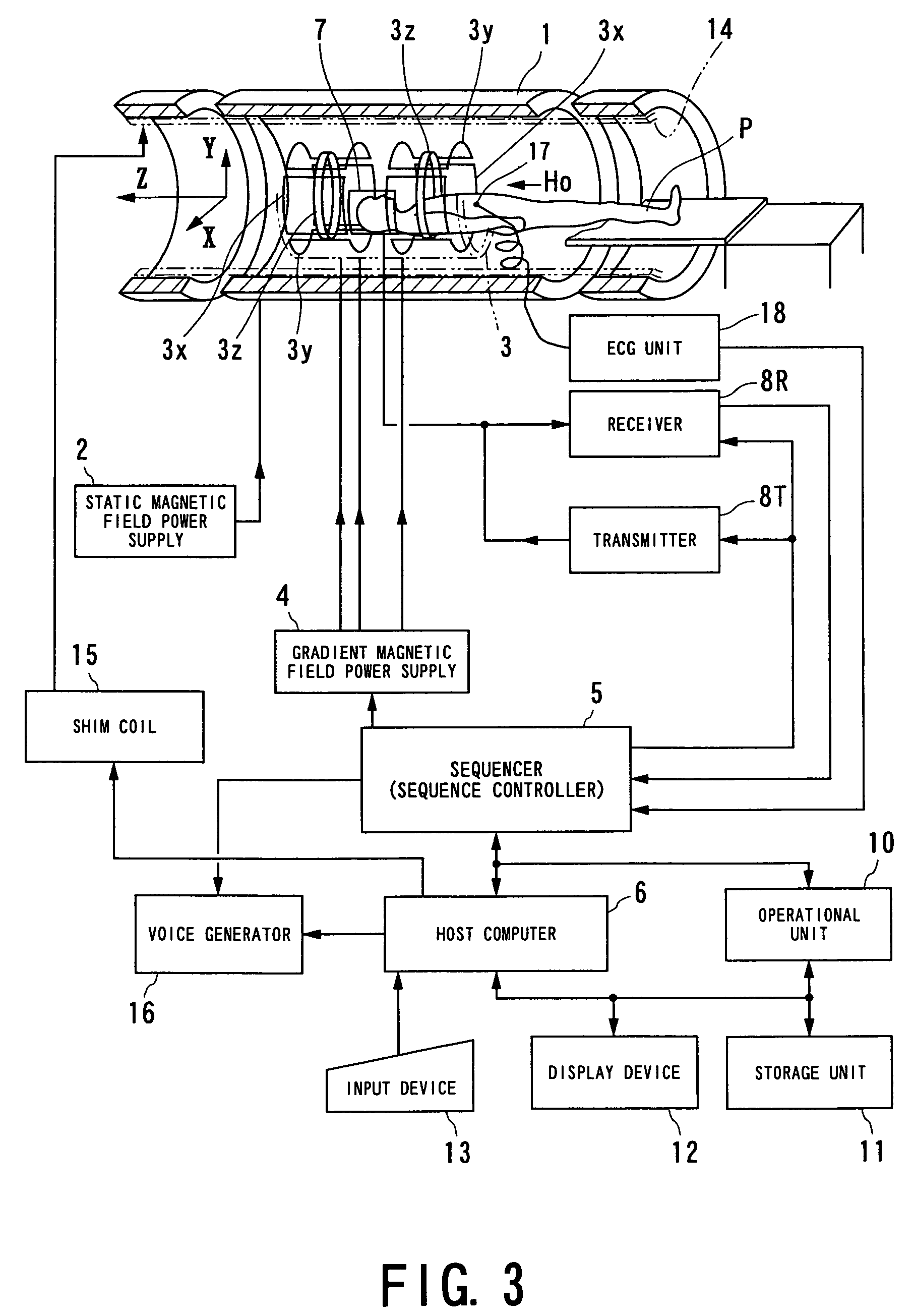
[0058]FIG. 3 shows an MRI apparatus according to the first embodiment. The MRI apparatus is furnished with a function of performing ASL imaging of various types of the invention.

[0059]Initially, the schematic configuration of the MRI apparatus will be described.

[0060]The MRI apparatus includes a patient couch portion on which the subject P is laid down, a static magnetic field generating portion generating a static magnetic field, a gradient magnetic field generating portion appending position information to a static magnetic field, a transmission and reception portion transmitting and receiving a high frequency signal, and a control and operation portion responsible for the control of the overall system and image reconstruction.

[0061]The static magnetic field generating portion includes a magnet 1, for example, of a super-conducting type, and a static magnetic field power supply 2 s...

second embodiment

[0106]An MRI apparatus according to a second embodiment of the invention will now be described with reference to FIG. 13. For the MRI apparatus of this embodiment, the same or equivalent components as those of the MRI apparatus according to the first embodiment above are labeled with the same reference numerals, and the description of these components is omitted or simplified (the same can be said in third and following embodiments described below).

[0107]The MRI apparatus according to the second embodiment is characterized in that it is furnished with a function of performing the ASL imaging of the invention, and in particular, it is able to address a blood flow velocity in a wider range.

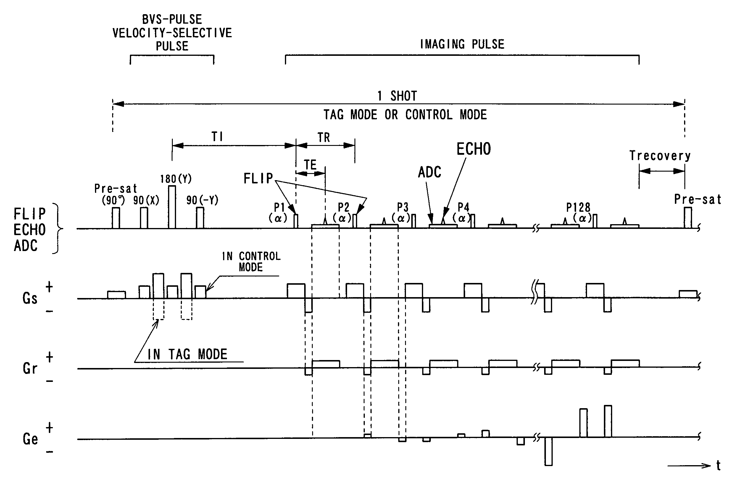
[0108]The ASL imaging performed in the second embodiment is a technique of reinforcing the BVS-ASL technique described above. When the BVS-ASL technique described above is performed solely, an artery having a high flow velocity outside the slab tagged by the velocity-selective pulse: BVS-pulse, BVS-...

third embodiment

[0118]An MRI apparatus according to a third embodiment of the invention will now be described with reference to FIG. 15.

[0119]The ASL imaging performed by the MRI apparatus of this embodiment is characterized in that it performs slab selection although it is the non-slice-selective ASL imaging technique of the unipolar-VENC type.

[0120]In order to realize such a characteristic, as is shown in FIG. 15, a pulse sequence is formed so that slab selection is performed with the use of a GMN (gradient moment nulling) pulse as the velocity-selective pulse: BVS-pulse.

[0121]When the slab selection is performed, the effect of the velocity encode (causing a phase to shift at a given velocity or higher) takes place in the control mode, and for this reason, the gradient magnetic field pulse for the slab selection is set to the GMN pattern. On the tag mode side, it is formed to give the velocity encode by the MPG pulse as with the embodiments above. This makes it possible to save the magnetization ...


PUM


Abstract

An MRI apparatus obtains an ASL (Arterial Spin Labeling) image of a region to be imaged in a subject by performing a scan to the region to be imaged independently in a control mode and in a tag mode according to a pulse sequence based on an ASL technique. The pulse sequence includes a velocity-selective pulse, BVS (Band-limited Velocity-Selective)-pulse, that selectively excites magnetization spins in a blood flow passing through the region to be imaged and having a constant velocity range for the spins to undergo transition to transverse magnetization, and then performs excitation to cause the transverse magnetization to flip back to longitudinal magnetization. The velocity-selective pulse is formed in such a manner that the transverse magnetization excited in each of the control mode and the tag mode gives rise to a phase shift in an opposite polarity upon velocity-selective excitation.

Description

BACKGROUND OF THE INVENTION[0001]1. Technical Field of the Invention[0002]The present invention relates to imaging based on the ASL (Arterial Spin Labeling) technique, ASL imaging, capable of providing images of perfusion (tissue blood flows) or blood vessels non-invasively without administrating a contrast medium to the subject. More particularly, the invention relates to an MRI (Magnetic Resonance Imaging) apparatus and the ASL imaging technique capable of performing the ASL imaging that reduces errors induced by a time needed for a blood flow to pass through the path from the label region to the tissue of interest in the imaging region (that is, transit delay time), which is intrinsic to the slice-selective ASL technique.[0003]The ASL technique referred to herein means the general spin labeling technique in the broad sense.[0004]2. Related Arts[0005]Magnetic resonance imaging is a technique involving magnetically exciting nuclear spins in a subject laid in a static magnetic field...

Claims


Application Information

Patent Timeline
IPC IPC(8): G01V3/00A61B5/055G01R33/48G01R33/563
CPCG01R33/56308G01R33/56316
Inventor KIMURA, TOKUNORI
Owner TOSHIBA MEDICAL SYST CORP
Why Eureka
Try Eureka