

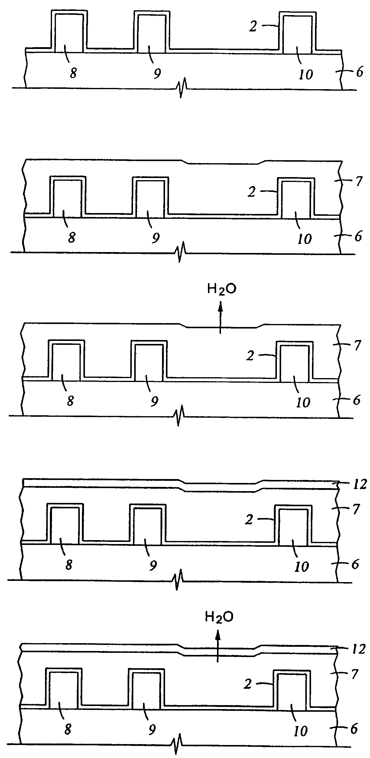
Techniques promoting adhesion of porous low K film to underlying barrier layer
a low-k film, porous technology, applied in the direction of coatings, solid-state devices, chemical vapor deposition coatings, etc., can solve the problems of increasing parasitic capacitance between devices, reducing the response time of devices, and damage to device structures, so as to improve the adhesion of porous low-k films to underlying barrier layers, the effect of enhancing the heating of the barrier interfa
- Summary
- Abstract
- Description
- Claims
- Application Information
AI Technical Summary
Benefits of technology
Problems solved by technology
Method used
Image

Examples
examples
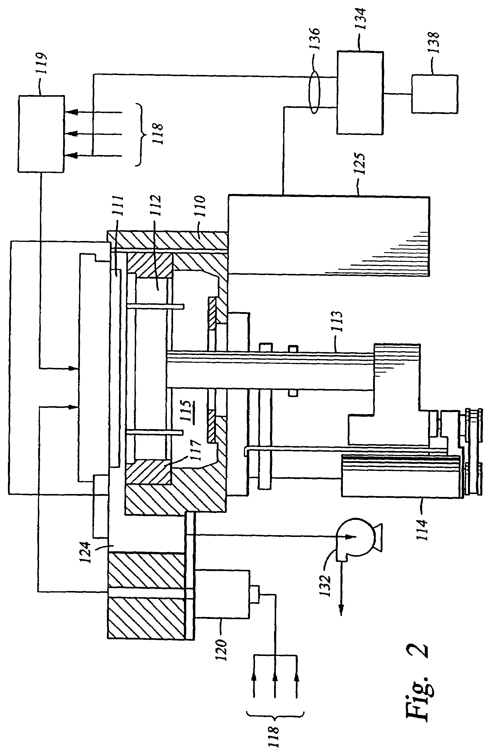
[0130]The following examples demonstrate deposition of a nano-porous silicon oxide based film having dispersed microscopic gas voids. This example is undertaken using a chemical vapor deposition chamber, and in particular, a CENTURA “DLK” system fabricated and sold by Applied Materials, Inc., Santa Clara, Calif.
Silicon Compound Having Silicon Containing and Thermally Labile Imparting Components (Hypothetical)
[0131]A nano-porous silicon oxide based film is deposited at a chamber pressure of 1.0 Torr and temperature of 30° C. from reactive gases which are vaporized and flown into the reactor as follows:
[0132]
methylsilyl-2-furyl ether, at 150 sccmnitrous oxide (N2O), at1000 sccm
[0133]Prior to entering the chamber, the nitrous oxide is dissociated in a microwave applicator that provides 2000 W of microwave energy. The substrate is positioned 600 mil from the gas distribution showerhead and the reactive gases are introduced for 2 minutes. The substrate is then heated over a time period o...
PUM
| Property | Measurement | Unit |
|---|---|---|
| feature sizes | aaaaa | aaaaa |
| feature sizes | aaaaa | aaaaa |
| dielectric constant | aaaaa | aaaaa |
Abstract
Description
Claims
Application Information