Interferometric method and apparatus for measuring physical parameters

a technology of interferometry and physical parameters, which is applied in the direction of heat measurement, force measurement by measuring optical property variation, instruments, etc., can solve the problems of high cost of pressure sensors with adequate flow determination performance (e.g. permanent quartz gauges), marginal temperature resolution of dts systems, especially in extended reach drilling wells

Inactive Publication Date: 2009-06-16
SENSOR HIGHWAY LTD
View PDF7 Cites 62 Cited by
  • Summary
  • Abstract
  • Description
  • Claims
  • Application Information

AI Technical Summary

Benefits of technology

[0017]In both cases the effect is to provide two independent interferometric arrays by means of a single fiber, therefore doubling the number of measurements available from which to obtain the optical path length and to separate the effects of multiple measurands.
[0044]In apparatus embodying the present invention the source means are preferably also operable to launch light at a fixed wavelength and at a varying wavelength into the fiber, the signal processing means being operable to use the interference signal from interrogation at the fixed wavelength to determine high frequency phase changes. In such a case the apparatus may further comprise an auxiliary optical fiber for deployment through the region of interest, reflectors being arrayed along the fiber to form an auxiliary array of sensor elements, the source means being operable to launch the fixed wavelength, signal into the auxiliary fiber. Preferably, the auxiliary fiber has a coating designed to enhance acoustic sensitivity. The apparatus embodying the present invention may also launch light at a variable wavelength concurrently with the launch of the fixed wavelength. The signal processing means may be further operable to use the high frequency phase changes to correct for dynamic errors in the returned optical interference signals.

Problems solved by technology

For much higher flow rates some information can be gained from frictional heating effects, but these are very small and the temperature resolution of DTS systems, especially in extended reach-drilling wells, is marginal.
Moreover, the DTS is relatively slow when set up for best resolution at long range.
However, pressure sensors with adequate performance for flow determination (e.g. permanent quartz gauges) are expensive and have only limited multiplexing capability.
Owing to the AC nature of the signal processing, many problems that are encountered in static measurements are circumvented.
One problem is that interferometric sensors provide a periodic response to the measurand and their answer is thus ambiguous.
In the typical path length between reflectors, there exist a very large number of fringes and it is then difficult to determine on which fringe the interferometer is presently sited.
However, unless the measurement system is able to determine the fringe order, this very high resolution is meaningless.

Method used


Image

  • Interferometric method and apparatus for measuring physical parameters
  • Interferometric method and apparatus for measuring physical parameters
  • Interferometric method and apparatus for measuring physical parameters

Examples


Embodiment Construction

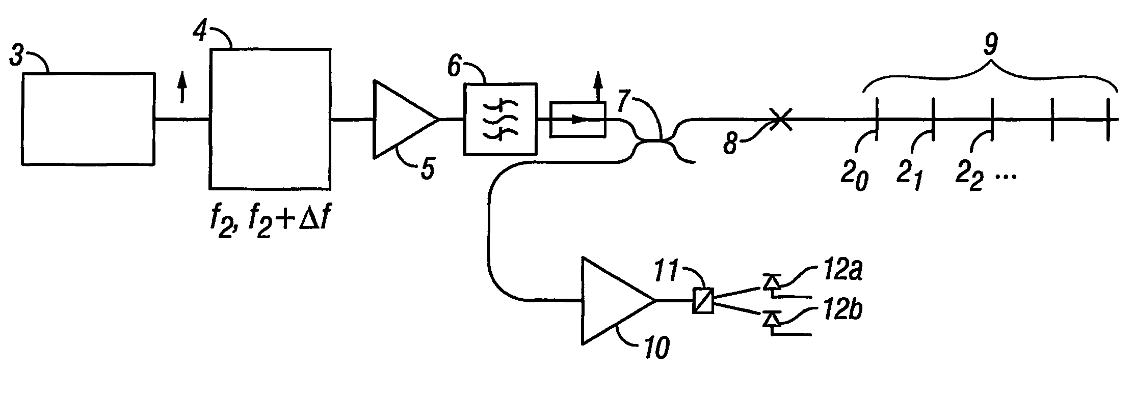
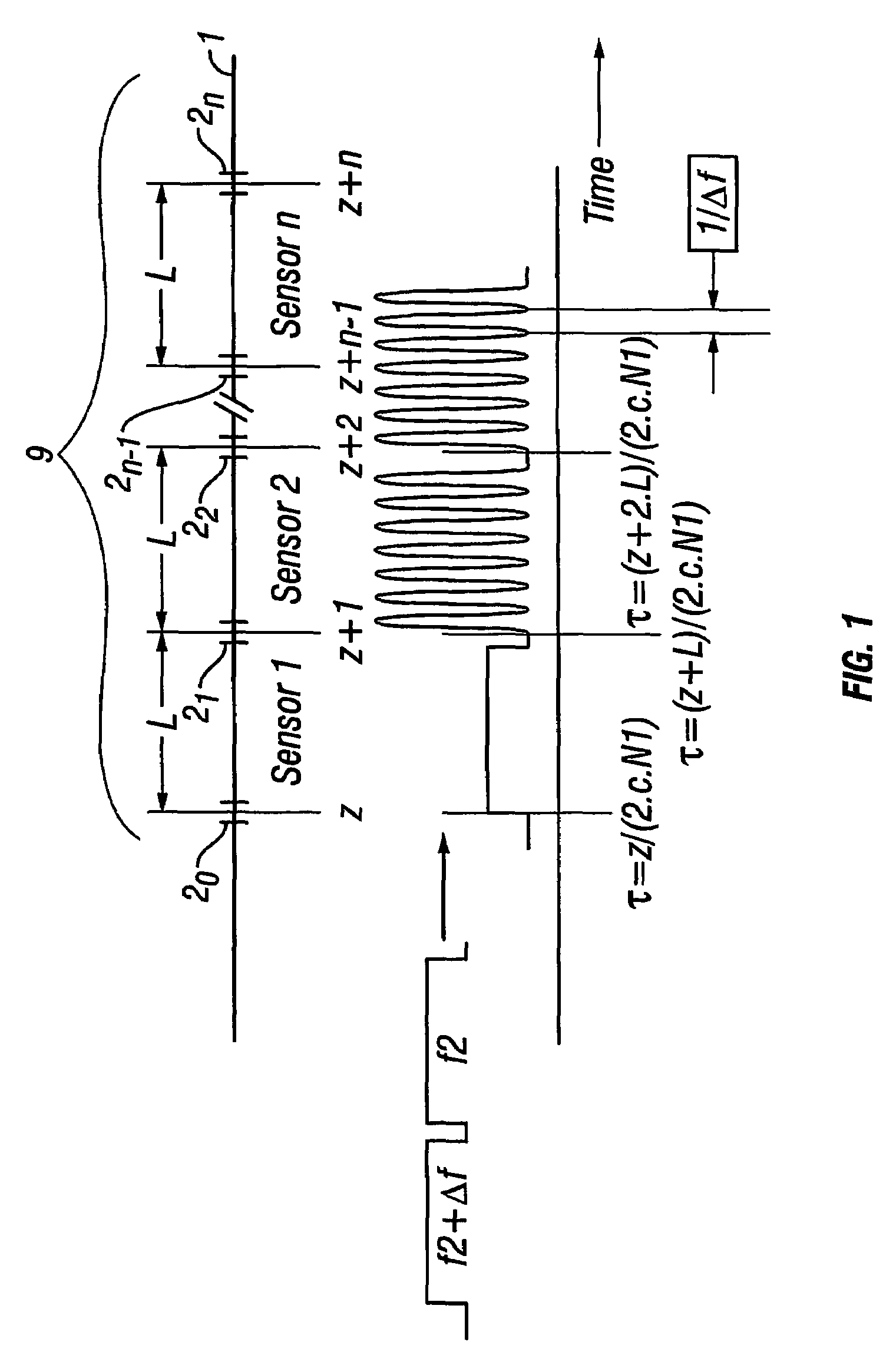
[0054]FIG. 1 illustrates an array of reflectors 20, 21, . . . 2n, separated by a distance L (approximately constant), imposed onto an optical fiber. The section of fiber between each pair of reflectors 20, 2l, etc. constitutes a sensor element. The reflectors are intended to be quite weak, for example of order 0.1% reflectivity, partly to reduce losses to subsequent sensor elements, but also to reduce cross-talk between the elements.

[0055]Cross-talk between adjacent sensor elements is a seriously limiting factor in acoustic sensor arrays in the purely reflectometric arrangement. However, the simplicity of the arrangement, including the reduced number of fibers to be taken to the surface and absence of components such as downhole couplers make it extremely attractive in the present context. The trade-off is that the reflectivity of each reflector must be reduced to limit cross-talk, which of course then impacts on the signal-to-noise ratio that can be achieved. However in this case, ...


PUM

PropertyMeasurementUnit
temperatureaaaaaaaaaa
wavelengthaaaaaaaaaa
reflectivityaaaaaaaaaa

Abstract

A method of measuring a selected physical parameter at a location within a region of interest comprises the steps of: launching optical pulses at a plurality of preselected interrogation wavelengths into an optical fiber (1) deployed along the region of interest, reflectors (20, 21, 2n) being arrayed along the optical fiber (1) to form an array (9) of sensor elements, the optical path length between the said reflectors (2) being dependent upon the selected parameter; detecting the returned optical interference signal for each of the preselected wavelengths; determining from the optical interference signal the absolute optical path length (L) between two reflectors (2) at the said location; and determining from the absolute optical path length (L) the value of the selected parameter at the said location; wherein the step of determining the absolute optical path length (L) comprises carrying out a process in which the phase difference between the interference signals for a pair of the preselected wavelengths is estimated using an estimated value for the optical path length (L), the estimated phase difference is used to estimate the phase at each of those wavelengths, and the phase thus obtained is used to revise the estimated value for the optical path length (L), the process being repeated for some or all remaining wavelength pairs in sequence, on the basis of the optical path length (L) estimated for the immediately preceding pair in the sequence, thereby to progressively revise the optical path length (L) until it is know to a desired level of accuracy.

Description

BACKGROUND[0001]The present invention relates to an interferometric method and apparatus for measuring physical parameters.[0002]Distributed temperature sensors (DTS) are known in which an optical fiber is deployed through a region of interest, light is launched into the fiber, and backscattered optical radiation is used to determine the temperature variation along the fiber. Such distributed temperature sensors have proven to be useful in oil production at determining, for example, flow contributions from different oil producing zones, identifying the location of the ingress of other fluids and the position at which gas breaks out. However, the interpretation of temperature data relies on the contrast between the thermal profile of a flowing well and the geothermal gradient. In those cases where the geothermal gradient is small (e.g. in a horizontal well), then the information may be obtained by inducing a thermal event, which can be tracked, thus revealing the local flow rate. Thi...

Claims


Application Information

Patent Timeline
Patent Type & Authority Patents(United States)
IPC IPC(8): G01B9/02G01D5/353G01K11/32G01L1/24
CPCG01D5/35383G01K11/32G01L1/246E21B47/123E21B47/065E21B47/07E21B47/135G01L1/247
Inventor HARTOG, ARTHUR H.
Owner SENSOR HIGHWAY LTD
Why Eureka
Try Eureka