Methods for reducing carbon contamination when melting highly reactive alloys

a technology of highly reactive alloys and carbon contamination, which is applied in the direction of manufacturing tools, furniture, lighting and heating apparatus, etc., can solve the problems of high reactive titanium aluminide (tial), contaminating the titanium alloy, and difficult to melt these highly reactive alloys, so as to reduce carbon contamination and reduce carbon contamination

Inactive Publication Date: 2009-09-01
GENERAL ELECTRIC CO
View PDF17 Cites 16 Cited by
  • Summary
  • Abstract
  • Description
  • Claims
  • Application Information

AI Technical Summary

Benefits of technology

[0006]Embodiments herein generally relate to methods for reducing carbon contamination when melting highly reactive alloys comprising providing a graphite crucible having an interior, applying at least a first protective layer to the interior of the graphite crucible, placing a highly reactive alloy into the crucible having the first protective layer, and melting the highly reactive alloy to obtain a melted alloy having reduced carbon contamination.
[0007]Embodiments herein also generally relate to methods for reducing carbon contamination when melting highly reactive alloys comprising providing a graphite crucible having an interior, applying a first protective layer to the interior of the graphite crucible, applying a second protective layer to the interior of the graphite crucible, placing a highly reactive alloy into the crucible having the first protective layer, and melting the highly reactive alloy to obtain a melted alloy having reduced carbon contamination.

Problems solved by technology

However, difficulties can arise when melting these highly reactive alloys due to the reactivity of the elements in the alloy at the temperatures needed for melting to occur.
As previously mentioned, while most induction melting systems use refractory alloy oxides for crucibles in the induction furnace, alloys such as titanium aluminide (TiAl) are so highly reactive that they can attack the refractory alloys present in the crucible and contaminate the titanium alloy.
Similarly, if graphite crucibles are employed, both the titanium and the aluminide can dissolve large quantities of carbon from the crucible into the titanium alloy, thereby resulting in contamination.
Such contamination results in the loss of mechanical properties of the titanium alloy.
Moreover, while cold crucible melting offers metallurgical advantages for the processing of the highly reactive alloys described previously, it also has a number of technical and economic limitations including low superheat, yield losses due to skull formation, high power requirements and a limited melt capacity.
These limitations can restrict its commercial viability.

Method used


Image

  • Methods for reducing carbon contamination when melting highly reactive alloys
  • Methods for reducing carbon contamination when melting highly reactive alloys
  • Methods for reducing carbon contamination when melting highly reactive alloys

Examples


Embodiment Construction

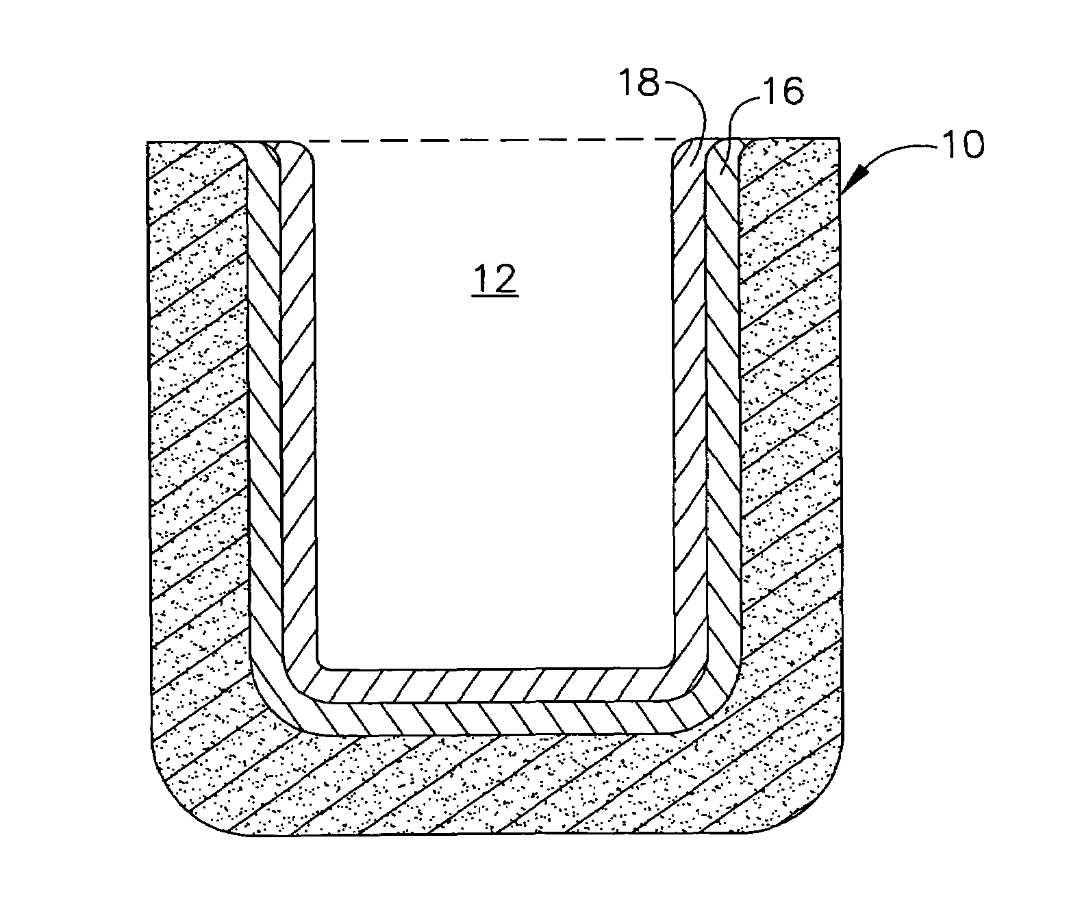
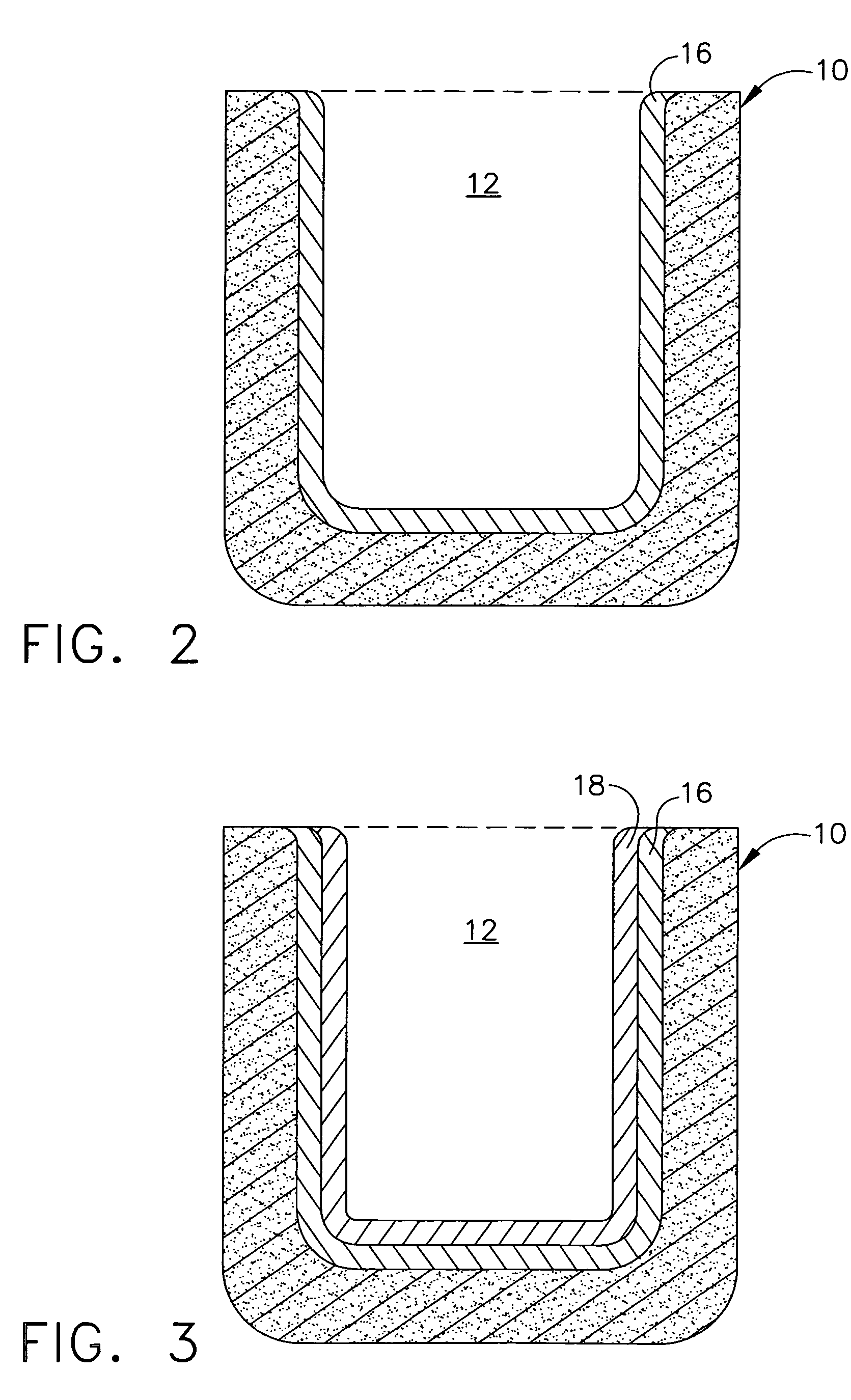
[0013]Embodiments described herein generally relate to methods for reducing carbon contamination when melting highly reactive alloys. In particular, embodiments herein relate to methods for using graphite crucibles having at least one protective layer to melt highly reactive alloys to produce a melted alloy having a reduced amount of contamination as forth herein below.

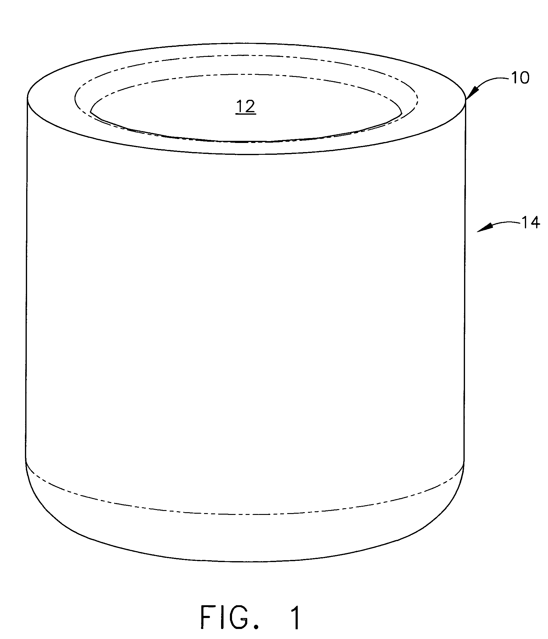
[0014]Turning to the figures, FIG. 1 illustrates one embodiment of an acceptable graphite crucible 10 for use herein. Graphite crucible 10 may be any graphite crucible known to those skilled in the art suitable for induction melting. Graphite crucible 10 can have an interior 12 for containing the alloy to be melted and an exterior 14.

[0015]Graphite crucible 10 may be used to melt highly reactive alloys such as, for example, those including the elements titanium, hafnium, iridium or rhenium, as well as advanced alloys including niobium, for example niobium silicide, or nickel, for example nickel aluminide. In one embod...


PUM

PropertyMeasurementUnit
temperatureaaaaaaaaaa
thicknessaaaaaaaaaa
thicknessaaaaaaaaaa

Abstract

Methods for reducing carbon contamination when melting highly reactive alloys involving providing a graphite crucible having an interior, applying at least a first protective layer to the interior of the graphite crucible, placing a highly reactive alloy into the crucible having the first protective layer, and melting the highly reactive alloy to obtain a melted alloy having reduced carbon contamination.

Description

TECHNICAL FIELD[0001]Embodiments described herein generally relate to methods for reducing carbon contamination when melting highly reactive alloys. More particularly, embodiments herein generally describe methods for reducing carbon contamination when melting highly reactive alloys by using a graphite crucible having at least one protective layer therein.BACKGROUND OF THE INVENTION[0002]Induction melting generally involves heating a metal in a crucible made from a non-conductive refractory alloy oxide until the charge of metal within the crucible is melted down to liquid form. When melting highly reactive metals such as titanium or titanium alloys, vacuum induction melting using cold wall or graphite crucibles is typically employed.[0003]However, difficulties can arise when melting these highly reactive alloys due to the reactivity of the elements in the alloy at the temperatures needed for melting to occur. As previously mentioned, while most induction melting systems use refracto...

Claims


Application Information

Patent Timeline
Patent Type & Authority Patents(United States)
IPC IPC(8): C22B4/06B22D41/02F27B14/10
CPCF27B14/10C22C14/00
Inventor KELLY, THOMAS JOSEPHWEIMER, MICHAEL JAMESBEWLAY, BERNARD PATRICKGIGLIOTTI, JR., MICHAEL FRANCIS XAVIER
Owner GENERAL ELECTRIC CO
Why Eureka
Try Eureka