

Drop discharge apparatus, method for forming pattern and method for manufacturing semiconductor device
- Summary
- Abstract
- Description
- Claims
- Application Information
AI Technical Summary
Benefits of technology
Problems solved by technology
Method used
Image

Examples
embodiment mode 1
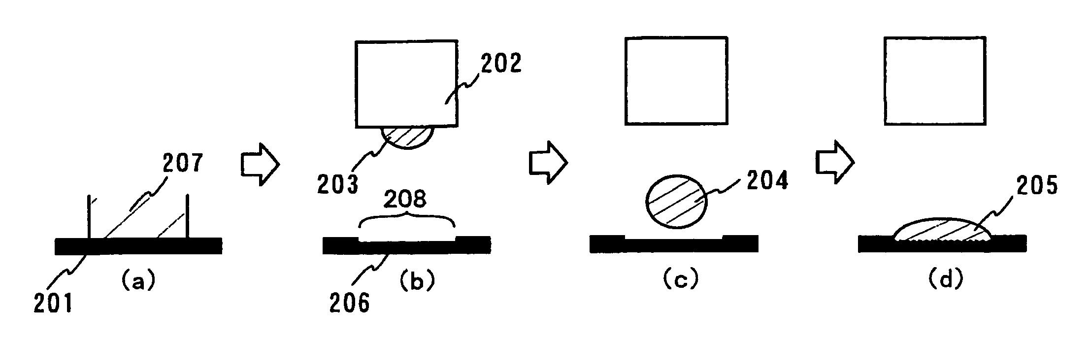
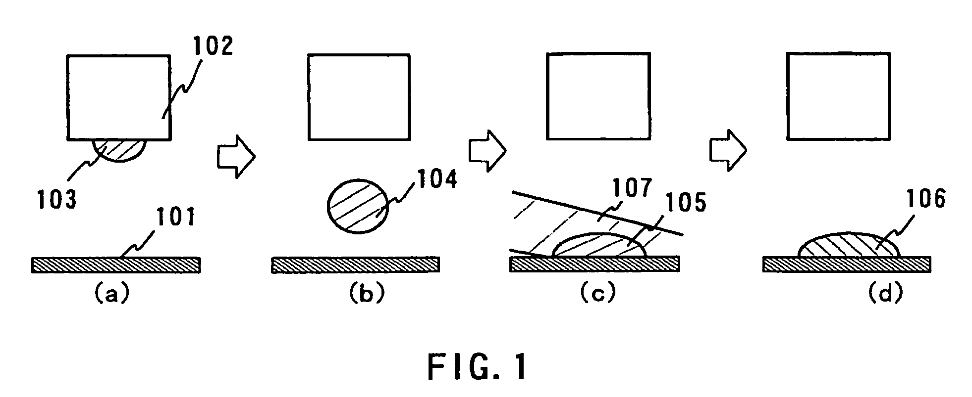
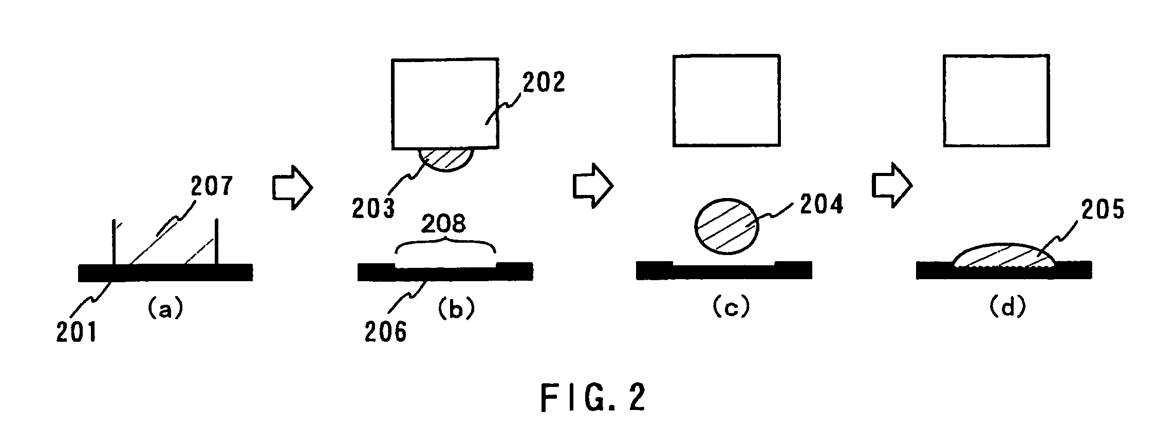
[0048]By use of FIGS. 1 to 4, a method for manufacturing a semiconductor device by use of a drop discharge apparatus in which pattern accuracy was heightened by carrying out irradiation of a laser beam will be explained. FIG. 1 typically shows a positional relationship in case that a substrate 101 to be processed and a front edge 102 of a drop discharge part and a drop 103 were viewed from the side. The drop discharge part is composed of a piezoelectric element (piezo element), a drop chamber, a discharge outlet (nozzle, head) and so on, and by applying a predetermined pulse voltage to the piezo element, the piezo element is deformed, to apply pressure to the drop chamber, and a drop is discharged from the discharge outlet.
[0049]As a drop to be discharged, used is a thing in which an electrically conductive material, which was properly selected from an element selected from tantalum (Ta), tungsten (W), titanium (Ti), molybdenum (Mo), aluminum (Al), copper (Cu), chromium (Cr), niobiu...
embodiment mode 2
[0059]One example of a drop discharge apparatus, which is used for carrying out the above-described embodiment mode, will be explained by use of FIG. 5 through FIG. 7.
[0060]A drop discharge apparatus, which is shown in FIG. 5, FIG. 6, has drop discharge means 501, 601 in the apparatus, and is such a thing that, by discharging solution by this, a desired pattern is formed on substrates 502, 602. Although it is not shown in the figure, in the drop discharge apparatus, a nozzle drive power supply and a nozzle heater for carrying out drop discharge are incorporated, and in addition, it is equipped with moving means for moving drop discharge means. In this drop discharge apparatus, as the substrate 502, 602, the substrates, which were described in the embodiment mode 1, can be applied.
[0061]In FIG. 5, FIG. 6, the substrates 502, 602 are carried from carry-in entrances 503, 603 in insides of housings 504, 604. The substrates 502, 602 are located on a transfer table which was equipped with...
embodiments
Embodiment 1
[0069]An embodiment 1 will be explained in detail by use of FIGS. 8(A)˜(D). In this regard, however, this invention is not limited to the following explanation, and it is easily understood to persons with skill in the art to be able to change variously, without departing from a theme of this invention and a scope thereof, details thereof. Therefore, this invention is not a thing which is interrupted to be limited to a description content of embodiments which are shown below. Here, a manufacturing process for forming a drive TFT and a switch TFT and a capacitance on an identical substrate by use of this invention will be explained.
[0070]As a substrate 800, it is possible to use the substrates which were described in the embodiment mode 1. In this embodiment, a glass substrate (Corning Corporation make, #7059) is used. Subsequently, on the substrate 800, a base film 801, which is composed of an insulating film, is formed. The base film 801 may be any one of a single layer ...
PUM
 Abstract
Description
Claims
Application Information