
Radiant syngas cooler

a technology of radiant synthesis gas and cooler, which is applied in the direction of combustible gas production, combustible gas purification/modification, steam generation using hot heat carriers, etc., can solve the problems of inability to meet the needs of igcc power plants that fire solid fuels, lower operating availability and reliability, and limited practicality of radiant synthesis gas cooler design. the cost of this component has not been reduced, and the existing solution is not effectiv

Inactive Publication Date: 2009-09-15
THE BABCOCK & WILCOX CO
View PDF9 Cites 53 Cited by
  • Summary
  • Abstract
  • Description
  • Claims
  • Application Information

AI Technical Summary

Problems solved by technology

IGCC power plants firing solid fuels have traditionally been higher capital cost and have had lower operating availability and reliability than competing solid fuel technologies such as pulverized coal combustion Rankine cycles.
Radiant synthesis gas cooler designs have a practical limitation of overall outside diameter due to the economics of pressure vessel containment and shipping size limitations to most power plant sites.
Existing solutions still have not reduced the cost of this component to a competitive level.
Some plant designs have utilized two coolers, reducing overall height but further increasing costs.
Additionally, redundant gasifiers, radiant coolers and convective coolers have been included in plant designs to improve plant operating availability, at a substantially higher cost.
Turbulence created in turns in the gas flue and at the inlet to the convective cooler has created a source of fuel ash fouling that can be difficult to manage.
Uncooled enclosures (General Electric, Conoco, others) have experienced premature failures and frequent replacement.
High availability with these designs typically requires a spare gasifier train, and / or firing the gas turbine on oil or gas at higher cost during repair time for the gasifier.
Some of these systems use low pressure, forced circulation cooling water systems that reject the heat outside of the power plant steam / water system, reducing efficiency.

Method used


Image

  • Radiant syngas cooler
  • Radiant syngas cooler
  • Radiant syngas cooler

Examples


first embodiment

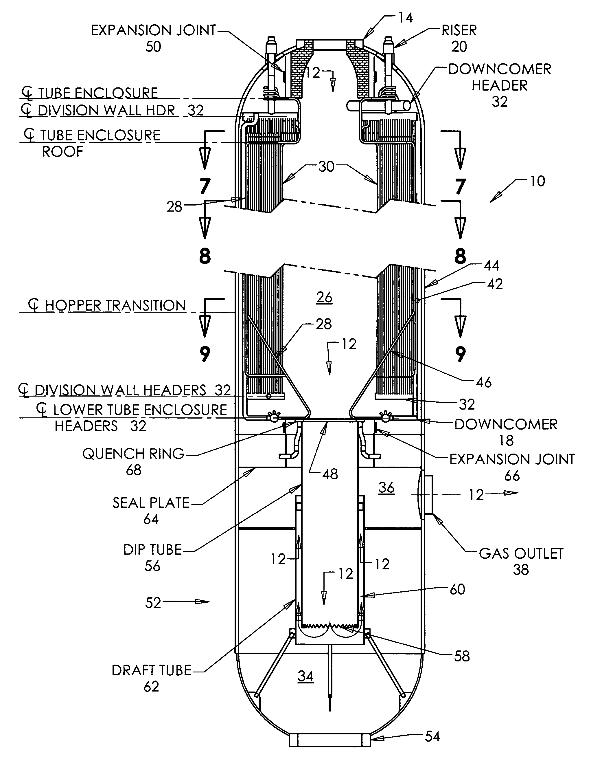
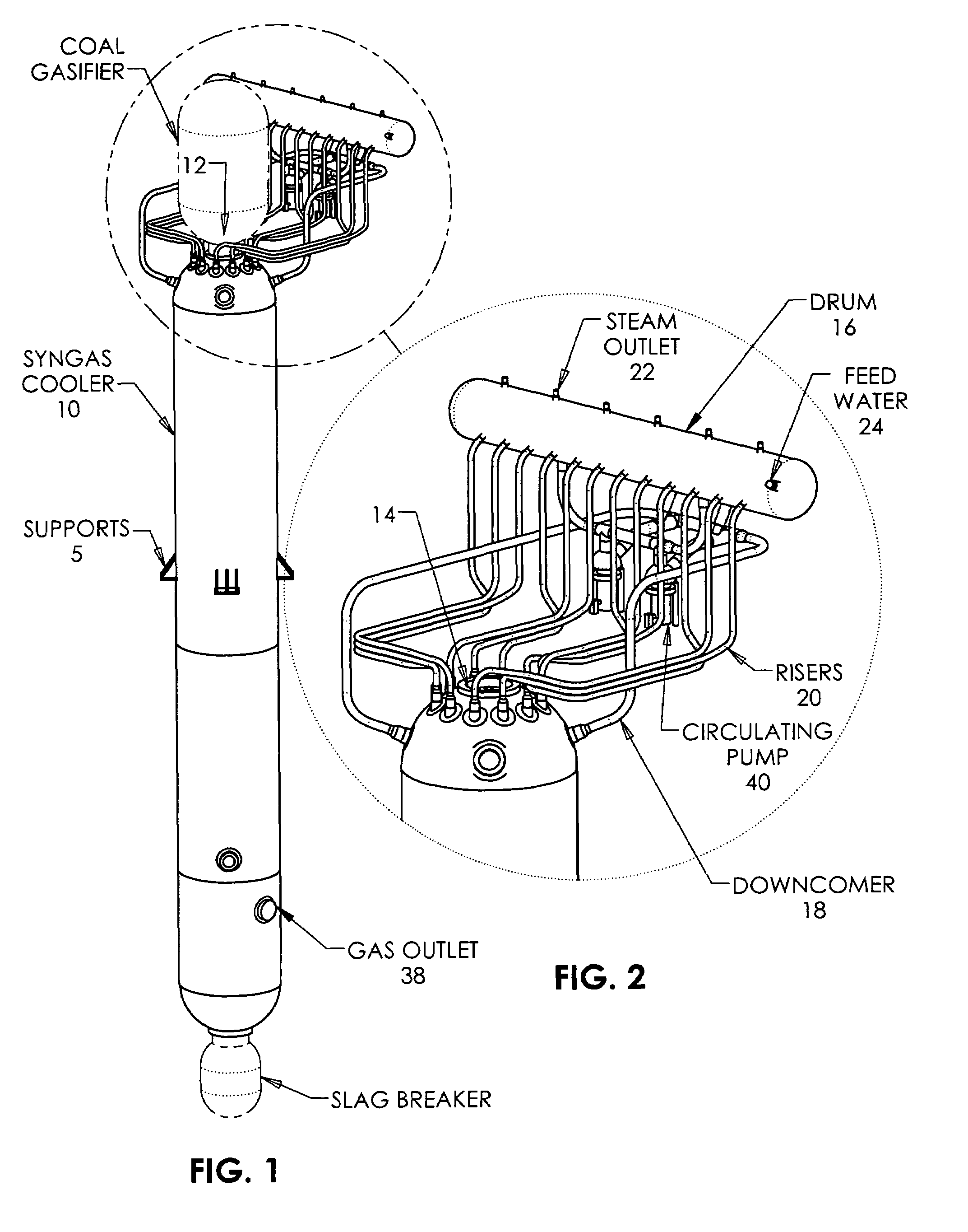
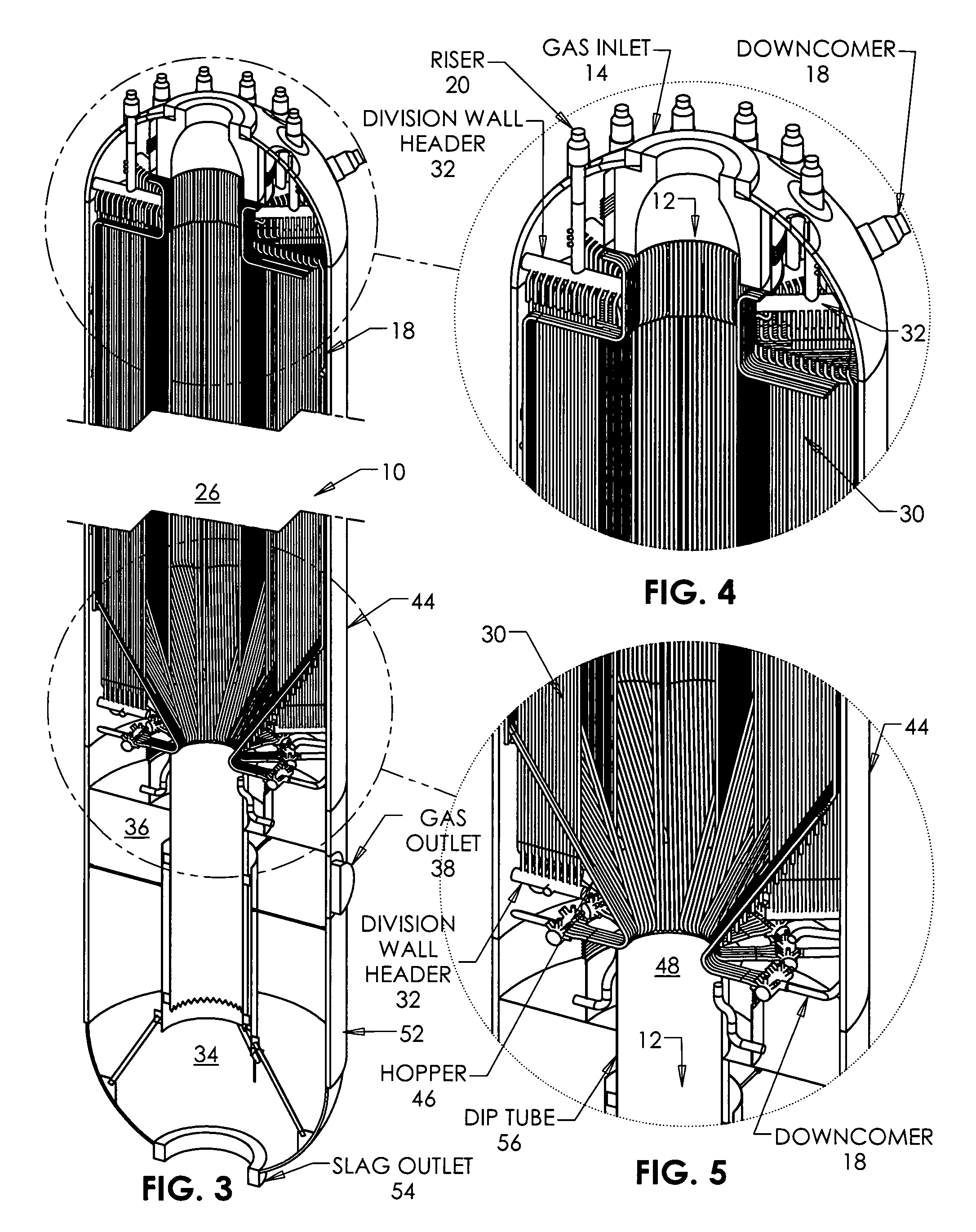
[0052]Referring to the drawings generally, wherein like reference numerals designate the same or functionally similar elements throughout the several drawings, and to FIGS. 1 and 2 in particular, there are shown perspective views of a radiant syngas cooler (RSC), generally designated 10, according to the present invention. The RSC 10 is typically a cylindrical vessel having its longitudinal axis oriented vertically. The RSC 10 is provided with hot synthesis gas 12 from a gasifier (shown in phantom in FIG. 1 and omitted for clarity in FIG. 2) at a synthesis gas inlet 14 provided at the top of the RSC 10. The RSC 10 is provided with supports 5 which transmit the load of the RSC 10 to adjacent support steel (not shown). As described later, the RSC 10 extracts heat from the synthesis gas 12 by means of fluid-cooled surfaces located within the RSC 10. These fluid-cooled surfaces are comprised of tubes and the working fluid within the tubes may be water, steam or a mixture thereof. A stea...

second embodiment

[0064]As shown in FIG. 10, the RSC 10 according to the present invention is disclosed, and which involves the placement of convection heat transfer surface 70 adjacent the dip tube means 56 in order to extract additional heat from the synthesis gas 12 prior to conveying the synthesis gas 12 through the synthesis gas outlet 38. Advantageously, the convection heat transfer surface 70 comprises one or more banks of tubes arranged so that the synthesis gas 12 flows over the outside of the tubes. This convection heating surface 70 can be water or steam cooled. The banks of convection heating surface 70 may be provided anywhere around the perimeter of the dip tube means 56 and the tubes may be in any orientation. The convection heating surface 70 may employ the same fluidic circuitry (an integrated cooling approach) as is employed in the steam generating surface comprising the flue walls 28 and radiant heat transfer surfaces 30, thus eliminating the need for a separate cooling system. Alt...


PUM

PropertyMeasurementUnit
heightsaaaaaaaaaa
pressureaaaaaaaaaa
heataaaaaaaaaa

Abstract

A radiant syngas cooler used to contain and cool the synthesis gas produced by coal gasification processes employs radiant and convection surfaces in a specific arrangement to achieve a cost-effective, compact design.

Description

FIELD AND BACKGROUND OF THE INVENTION[0001]The present invention relates generally to the field of coal gasification and, in particular, to a radiant synthesis gas (syngas) cooler for an Integrated Gasification Combined Cycle (IGCC) power plant. The radiant syngas cooler is used to contain and cool the synthesis gas produced by a coal gasification process used in the IGCC power plant.[0002]IGCC power plants firing solid fuels have traditionally been higher capital cost and have had lower operating availability and reliability than competing solid fuel technologies such as pulverized coal combustion Rankine cycles. Primary components to be improved upon to make IGCC more competitive include uncooled gasifiers and radiant and convective synthesis gas coolers. Radiant synthesis gas cooler designs have a practical limitation of overall outside diameter due to the economics of pressure vessel containment and shipping size limitations to most power plant sites. Within these limits to vess...

Claims


Application Information

Patent Timeline
Patent Type & Authority Patents(United States)
IPC IPC(8): C10J3/76
CPCC10J3/84C10J3/845C10J3/86C10K1/101F22B1/18F22B1/1838C10J3/76F22B21/06F28D7/163C10K1/04C10J3/526F22B1/1846Y02E20/18Y02E20/16
Inventor KRAFT, DAVE L.ALEXANDER, KIPLIN C.FRY, STEVEN R.DOYLE, THOMAS E.ALBRECHT, MELVIN J.
Owner THE BABCOCK & WILCOX CO
Learn More