Source phase sensitive transfer method and apparatus

a phase sensitive and source technology, applied in the direction of magnetostatic bodies, emergency power supply arrangements, cores/yokes, etc., can solve the problems of catastrophic consequences for the electrical power system of the facility, the potential single point of failure of the transfer switch in the system, and the inability to ensure the phase of the voltage waveform provided by each source, so as to reduce the amount of delay time

Active Publication Date: 2009-09-15
LAYERZERO POWER SYST
View PDF26 Cites 27 Cited by
  • Summary
  • Abstract
  • Description
  • Claims
  • Application Information

AI Technical Summary

Benefits of technology

[0011]The disadvantages of the prior art are overcome by the present invention of a source phase sensitive transfer method and apparatus. The present invention solves the problems associated with essentially instantaneous transfer by assuring that the transfer time is a function of the phase angle between the sources at the instant that a transfer is initiated. Whereas prior art SSTSs tried to minimize the amount of delay time, i.e., time when no source is connected to the load, the present invention purposely inserts a precisely timed amount of delay time into the transfer.
[0013]The present invention has particular advantages when employed in power supply systems that are connected to loads comprising transformers built of ferromagnetic materials. By avoiding instantaneous transfers and providing for a delay in the switching to a secondary power source, the present invention avoids the problems associated with transformer saturation, and the resulting draw of a large amount of current from the power source that can cause upstream circuit breakers to trip open, and uninterruptible power systems and engine generators to malfunction. In so doing, the present invention avoids consequences that can have devastating effects on a mission critical facility.
[0015]The purposeful insertion of delay time into the transfer sequence of an SSTS is counterintuitive to the premise that an SSTS should attempt to power the load as continuously as possible. However, it is clear that there are situations where the risk of causing widespread damage to a large mission critical facility outweighs the benefit of absolutely minimizing the transfer time associated with one SSTS and its load. The invention is thus useful in that it improves the reliability of the large-scale power system with respect to reliability without the invention. The present Information Technology Industry Council (ITIC) voltage-versus-time relationship expressing the requirements for powering mission critical loads allows for up to 20 milliseconds of zero voltage condition. Thus, the present invention provides transfers well within allowable zero voltage time limits.
[0017]The non-obviousness of the present invention is based on the counterintuitive notion that delay time inserted into SSTS transfers can actually improve the overall reliability of a mission critical power system, relative to systems where SSTS devices minimize delay time at under all circumstances. Only by careful understanding of the mechanism by which entire mission critical facilities can be compromised by transformer saturation, and by looking at the role of SSTS equipment in a non-obvious way, can one arrive at the realization that the invention solves the essential problem.

Problems solved by technology

Since the solid-state transfer switch represents the place in the power system where multiple redundant sets of power sources and wiring come together to power the load, the transfer switch is potentially a single point of failure in the system.
Such a connection, however brief, would have catastrophic consequences for the electrical power system of the facility.
One aspect of these sources is that there is often no guarantee that the phase of the voltage waveforms provided by each source is precisely in phase with the voltage provided by the other source or sources.
Although there are often circuits or equipment intended to maintain phase synchronization between the sources, these circuits or equipment represent single points of failure in the system, and tend to be unreliable.
This arrangement causes the transformer to be a potential single point of failure, but it is a risk that is often assumed in the interest of economy, and in view of the fact that transformers are generally very reliable devices.
The type of power system described thus far is common in practice, being used in a large number of existing mission critical facilities, although it has a very serious drawback that compromises its overall reliability.
When a transformer saturates, the impedance of the transformer drops sharply, resulting in the transformer drawing a large amount of current from its power source.
This saturation current can cause upstream circuit breakers to trip open, as well as causing the uninterruptible power systems and engine generators to malfunction.
Any of these consequences has devastating effects on a mission critical facility.
A power system as described above is vulnerable to failure when a SSTS creates a nearly instantaneous transfer between sources that are out of phase, where the load includes a ferromagnetic transfer.
The out-of-phase transfer has the consequence of potentially adding volt-seconds of flux to the transformer far in excess of design limits, initiating a cascade of failures in the power system.
Two consecutive positive half-cycles of voltage will exceed the transformer flux limit and start the cascade of failures.
This disastrous situation has been observed in practice.

Method used


Image

  • Source phase sensitive transfer method and apparatus
  • Source phase sensitive transfer method and apparatus
  • Source phase sensitive transfer method and apparatus

Examples


Embodiment Construction

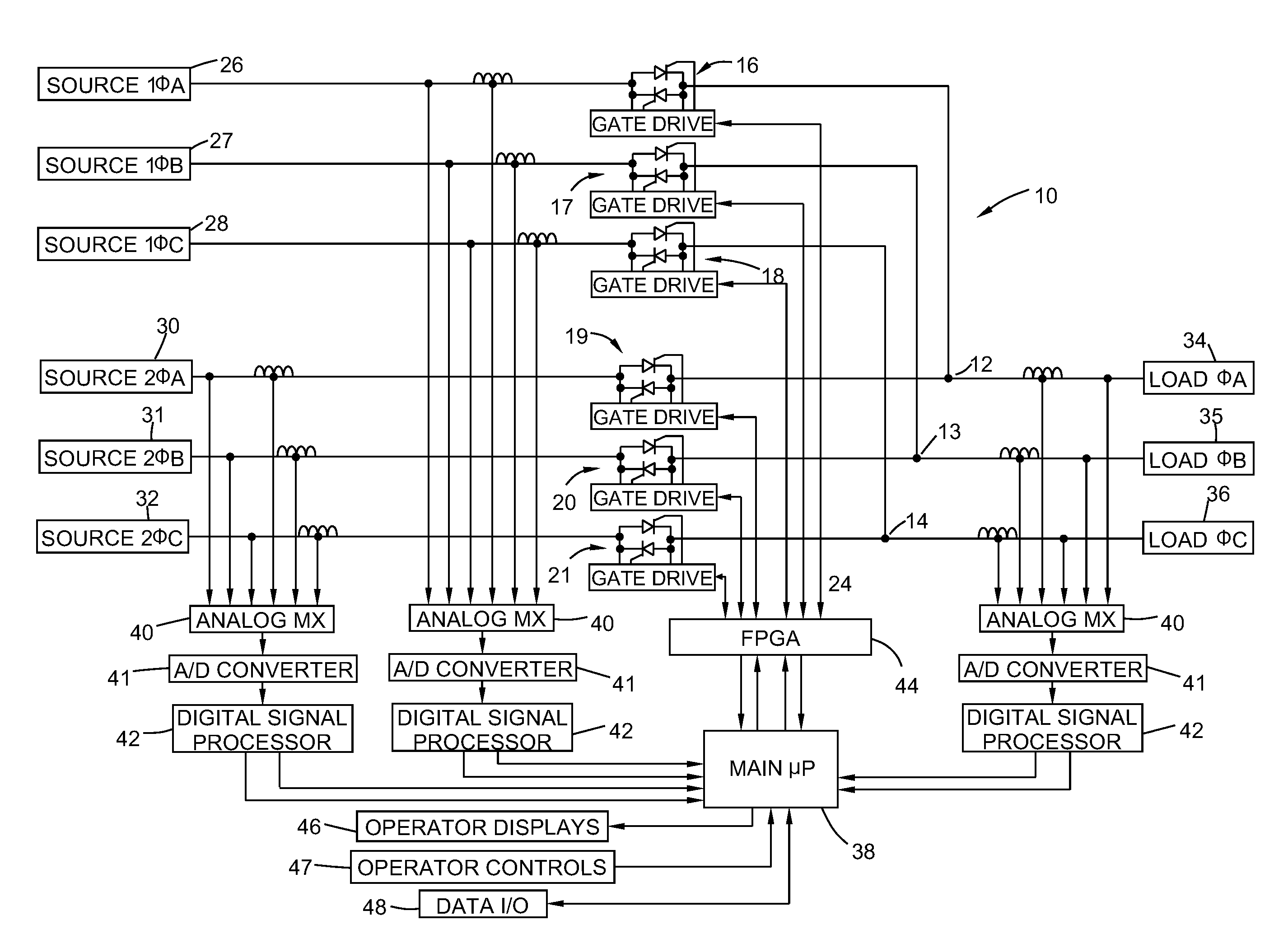
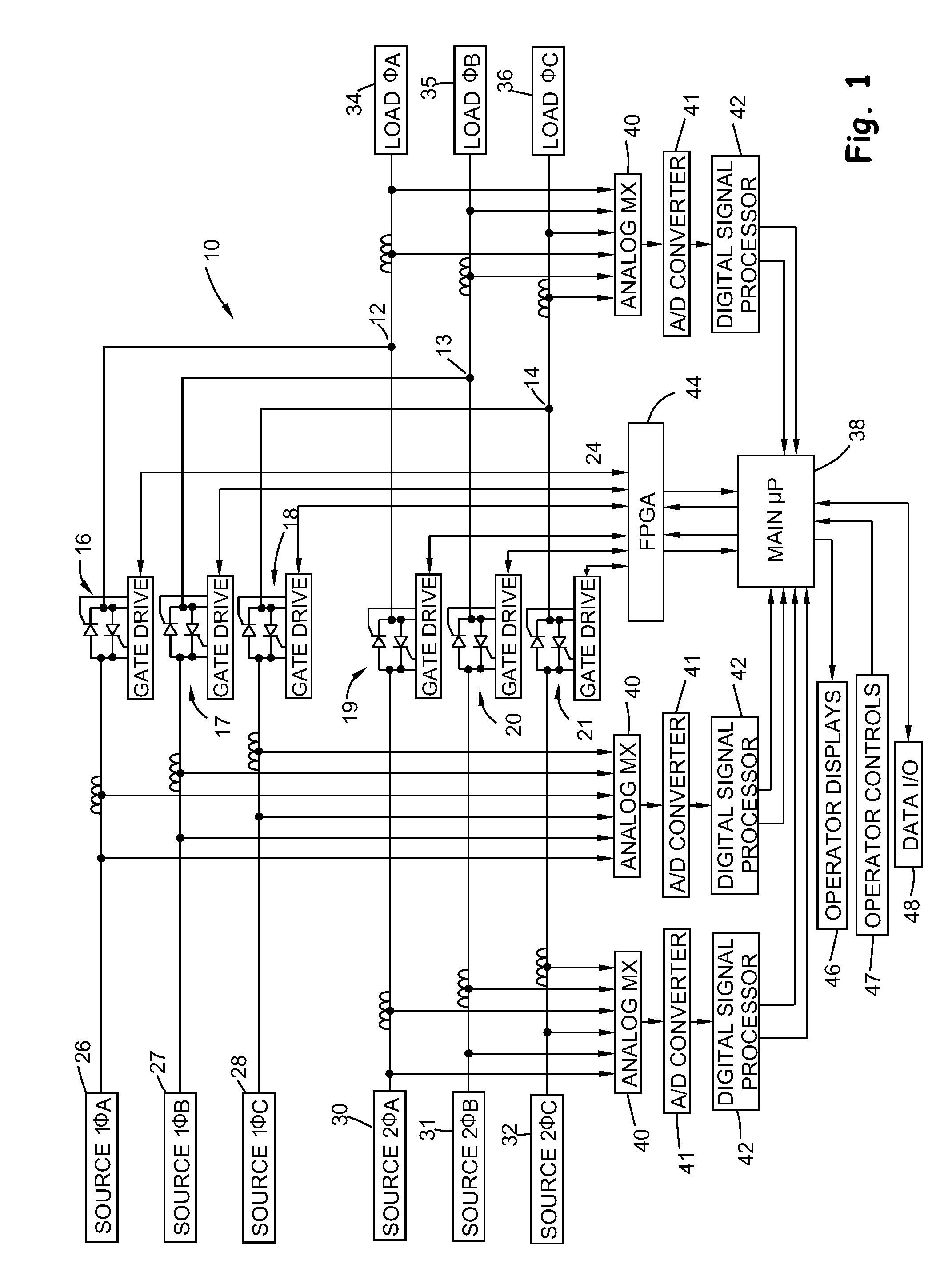
[0026]Referring more particularly to the drawings, and initially to FIG. 1, there is shown a block diagram of a control system 10 that controls application of power to a load 34-26 from either of two alternating current power sources 26-28 and 30-32. The control system 10 of FIG. 1 illustrates use of the invention with a three-phase power delivery system that has the capacity to switch two alternate power sources to a load under varying conditions. One possible use of the system 10 depicted in FIG. 1 is in a large computer center where it is important that at least some of the electrically powered equipment not lose power and hence a backup power is made available. Preferably, the system of the present invention is configured to handle two or more alternate power sources with three or more phases in each source, and the preferable system can handle as many as three different alternate power sources, each of which may have as many as five phases. However, for the purposes of simplify...


PUM


Abstract

A method and apparatus for transferring AC electrical power to a load from a first power source to a second power source provides for a time delay in the transfer to avoid problems associated with differences in the phases between the power sources. The phase of the voltage waveform from each power source is sensed continuously, and the phase difference is known at all times, so that it can be used when the transfer is necessary. The method and apparatus monitors the voltage from the first power source, and initiates the transfer from the first power source to the second power source in response to an unacceptable condition from the first power source. The second power source is connected only after waiting for a period of time corresponding to the appropriate time delay.

Description

FIELD OF INVENTION[0001]The present invention relates to a solid-state transfer system for providing multiple current paths between several power sources and a load that is energized by any of those sources. More specifically the invention relates to a solid-state transfer system and method for efficient switching between active current carrying devices in a way less likely to cause damage to circuits and components connected to the power sources or to the power sources themselves.BACKGROUND OF THE INVENTION[0002]It is often important and sometimes critical that a back-up power source be available in case a primary power source is either unavailable or degrades until it is not suitable for powering a load. A large computer center may, for example, have access to two or more separate sources of alternating current power for operating some or all of the equipment.[0003]Solid-state transfer switches (SSTS) are normally used in these mission critical environments, such as computer cente...

Claims


Application Information

Patent Timeline
Patent Type & Authority Patents(United States)
IPC IPC(8): H01H83/00H02H3/00H02J3/00H02J9/04
CPCH02J3/005H02J3/007
Inventor GALM, JAMES M.
Owner LAYERZERO POWER SYST
Why Eureka
Try Eureka