
Differential amplifier circuit and mixer circuit having improved linearity

a mixer circuit and amplifier circuit technology, applied in the field ofdifferential amplifier circuits, can solve the problem of weak rf circuit consisting of single-ended circuits, and achieve the effect of improving the linearity of the amplifier stag

Inactive Publication Date: 2009-10-13
INTEGRANT TECH
View PDF27 Cites 20 Cited by
  • Summary
  • Abstract
  • Description
  • Claims
  • Application Information

AI Technical Summary

Benefits of technology

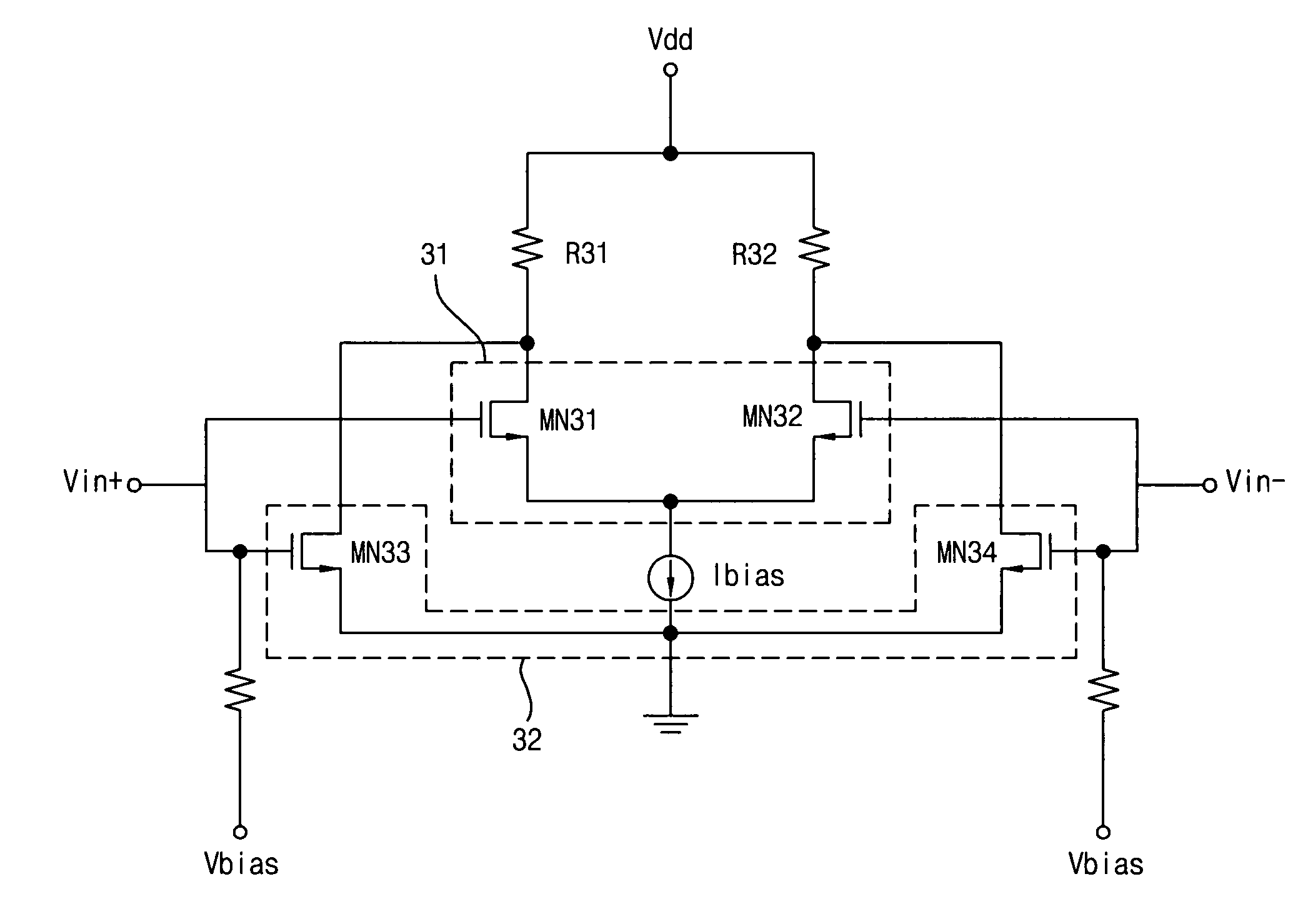
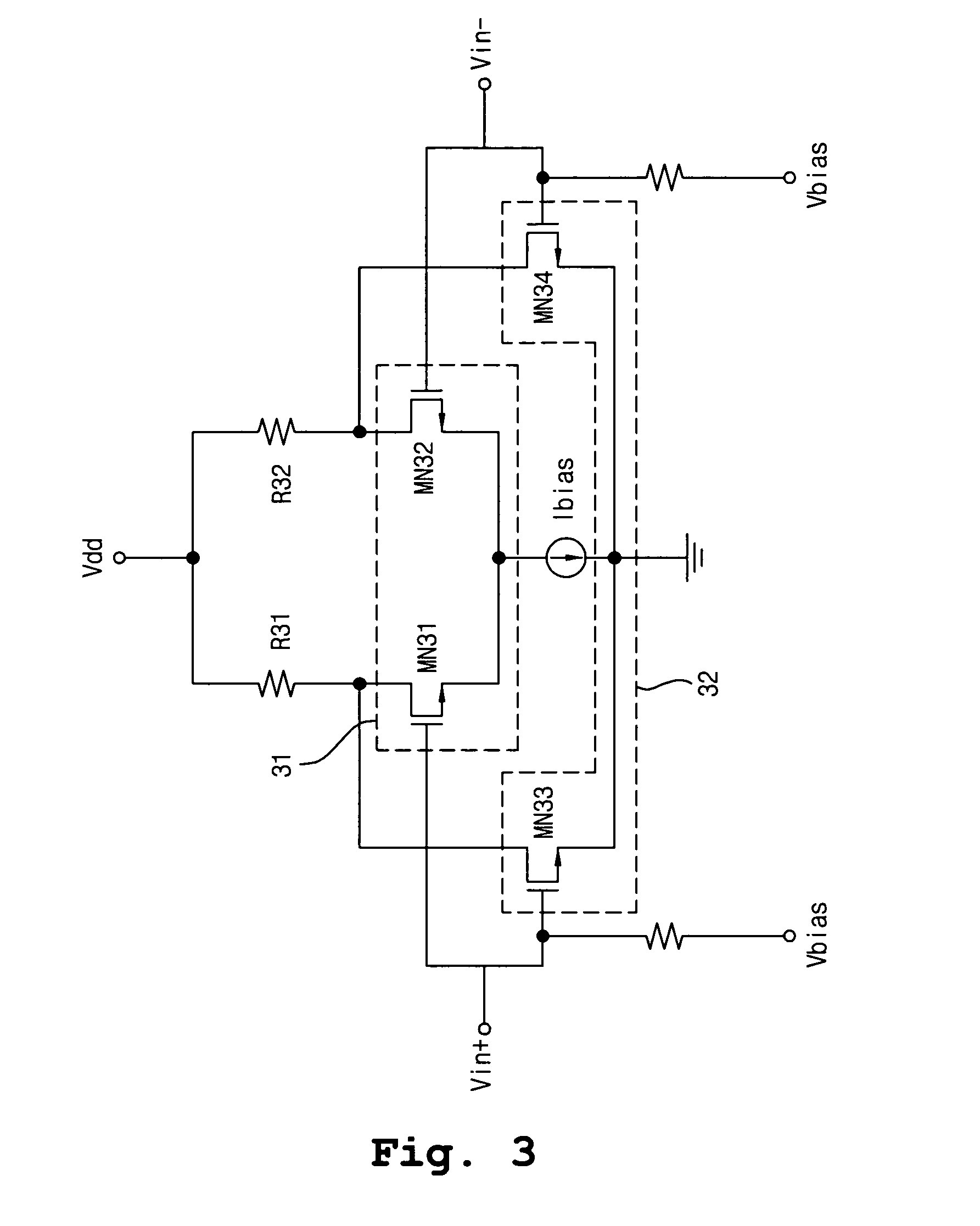
"The present invention provides a differential amplifier circuit that improves linearity while maintaining the advantages of a differential circuit. The circuit includes a main differential amplifier unit and an auxiliary differential amplifier unit, which form differential pairs to amplify the difference between input voltages. The circuit also includes a mixer circuit that uses a differential amplifier circuit to improve linearity. The mixer circuit includes first and second load stages, a main differential amplifier unit, and an auxiliary differential amplifier unit. The invention also provides a folded cascode mixer circuit and a double balance mixer circuit that improve the linearity of the amplifier stage. These improvements can be achieved without compromising the advantages of a differential circuit."

Problems solved by technology

A RF circuit consisting of a single-ended circuit is weak in problems, such as signal coupling or even order distortion, in a higher integrated circuit such as SOC (System on a Chip).

Method used


Image

  • Differential amplifier circuit and mixer circuit having improved linearity
  • Differential amplifier circuit and mixer circuit having improved linearity
  • Differential amplifier circuit and mixer circuit having improved linearity

Examples


Embodiment Construction

[0037]The present invention will now be described in detail in connection with preferred embodiments with reference to the accompanying drawings.

[0038]Further, MOSFET will be described as an example in the following description. It is, however, to be noted that the present invention can be applied to a bipolar junction transistor that can be used as an amplifier as well as MOSFET. Therefore, although MOSFET will be described as an example in this context, the present invention is not limited to MOSFET.

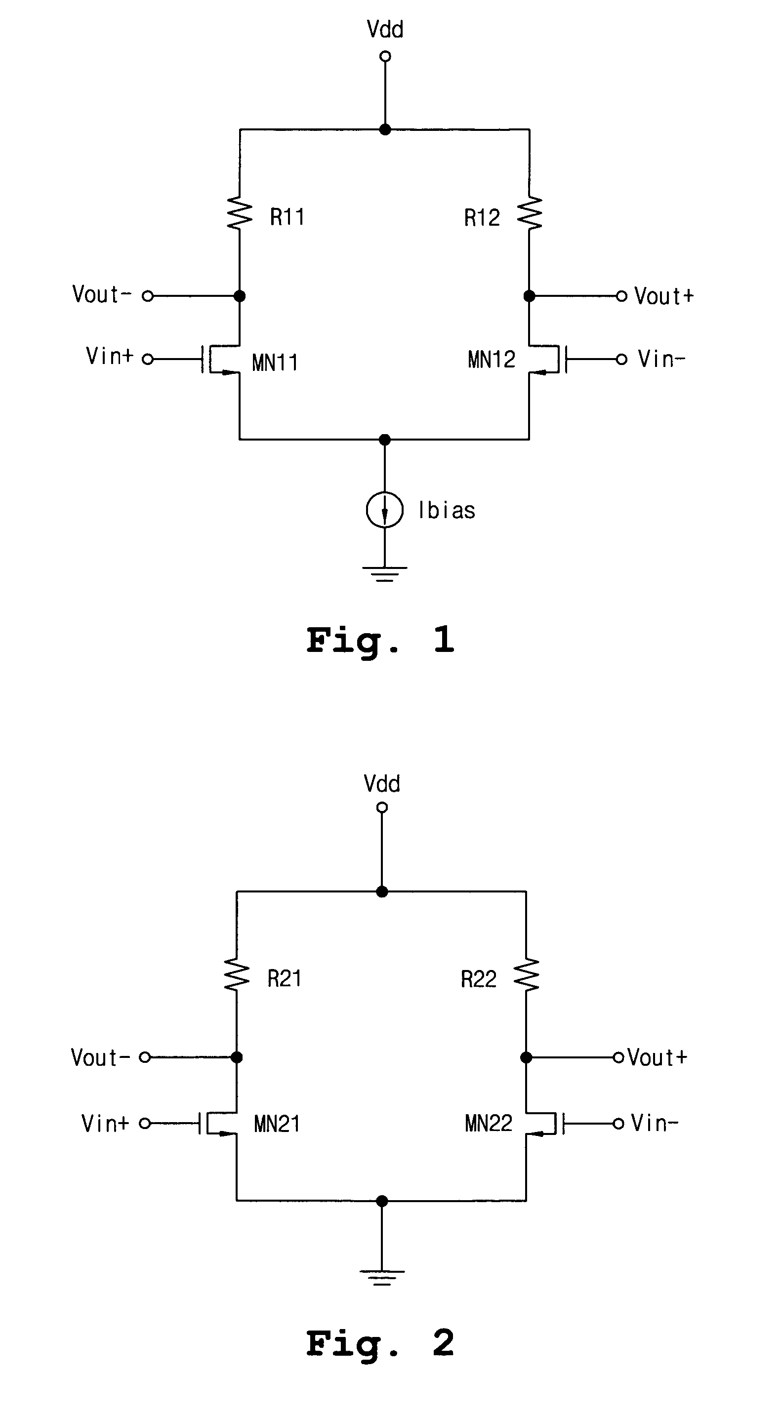
[0039]FIG. 1 is a circuit diagram of a fully differential amplifier (FDA) of a current-biased differential amplifier circuit among a differential amplifier circuit, which is to be proposed by the present invention.

[0040]Referring to FIG. 1, the FDA includes first and second load resistors R11, R12, first and second NMOS transistors MN11, MN12, and a bias current source Ibias. Generally, in a differential amplifier, the first and second load resistors R11, R12 are set to have the same r...


PUM


Abstract

The present invention relates to a differential amplifier and a mixer for improving the linearity. The differential amplifier circuit according to this present invention, includes first and second load stages each having a predetermined voltage value, a main differential amplifier unit having a first differential stage that forms a differential pair in such a way as to amplify a difference between a first input voltage and a second input voltage, and a constant current source, which has a predetermined current driving capability and is connected serially between a power source voltage terminal and a ground terminal, and a auxiliary differential amplifier unit having a second differential stage that forms a differential pair in such a way as to amplify a difference between a third input voltage and a fourth input voltage connected between the first load stage and a second load stage, and the ground, respectively.

Description

BACKGROUND OF THE INVENTION[0001]1. Field of the Invention[0002]The present invention relates to a differential amplifier circuit, and more particularly, to a differential amplifier circuit having improved linearity, and a mixer circuit including the differential amplifier circuit.[0003]2. Background of the Related Art[0004]A RF circuit consisting of a single-ended circuit is weak in problems, such as signal coupling or even order distortion, in a higher integrated circuit such as SOC (System on a Chip). In order to solve these problems, a differential circuit is employed. That is, the differential circuit is effective in solving the aforementioned problems since it has high CMRR (Common Mode Rejection Ratio) and IIP2 (Input 2nd Intercept Point).[0005]Further, in the RF circuit, the linearity is a very important factor. This has a close relation with a secondary differential coefficient (gm″) of the transconductance of the amplifier circuit.[0006]The applicant of this application fi...

Claims


Application Information

Patent Timeline
Patent Type & Authority Patents(United States)
IPC IPC(8): G06G7/12
CPCH03D7/1441H03F1/3211H03F3/45183H03D7/1458H03D7/1491H03D7/1433H03D2200/0047H03D2200/0043H03F3/45
Inventor KIM, TAE WOOKKIM, BONKEELEE, KWYRO
Owner INTEGRANT TECH
Learn More