Optical fiber coupling part and manufacturing method thereof

a technology of optical fiber and coupling parts, applied in the direction of manufacturing tools, instruments, lenses, etc., can solve the problems of significant troublesome conventional processes, achieve the effects of convenient alignment of axes, facilitate manufacturing, and large-scale production

Active Publication Date: 2009-10-13
TOYO SEIKAN GRP HLDG LTD
View PDF44 Cites 29 Cited by
  • Summary
  • Abstract
  • Description
  • Claims
  • Application Information

AI Technical Summary

Benefits of technology

[0021]The optical fiber coupling part of the present invention, in which the GRIN lens and the optical fiber are unified, effectively facilitates alignment of axes in coupling the semiconductor laser and the optical fiber. Additionally, fusion of the GRIN lens and the optical fiber enables automatic concordance of the axes of the GRIN lens and the optical fiber by a self-alignment effect resulting from a surface tension in fusion, effectively facilitates manufacture and allows large scale production. Since an adhesive is not used, problems of deterioration of optical characteristics, due to alteration of the adhesive by the increased temperature when high-intensity light enters, are not caused. Furthermore, coupling loss in the semiconductor laser module can be reduced by setting a refractive index distribution constant g of the GRIN lens within an appropriate range.

Problems solved by technology

As mentioned above, the conventional processes had been significantly troublesome because complex and subtle adjustment of the cores in multiaxial directions was required.

Method used


Image

  • Optical fiber coupling part and manufacturing method thereof
  • Optical fiber coupling part and manufacturing method thereof
  • Optical fiber coupling part and manufacturing method thereof

Examples


example 1

[0041]9.2 ml of 2N hydrochloric acid was added to a mixture of 75.5 ml of a silicon tetramethoxide and 183.4 ml of isopropanol, and stirred for 30 min., then 30.8 ml of a titanium tetra-n-butoxide was added. Subsequently, 0.01 N ammonia water was added to obtain a wet gel. The wet gel was aged at 50° C. for two days, and soaked in 6N hydrochloric acid for two hours, providing a concentration distribution of titanium in the gel. Then the gel was soaked in methanol to rinse hydrochloric acid in the gel. The gel was soaked in 6N hydrochloric acid for 20 minutes for the second provision of the concentration distribution, then soaked in methanol to rinse hydrochloric acid as with the first step, and dried. Subsequently, the gel was soaked in 6N hydrochloric acid for 8 minutes for the third provision of the concentration distribution, then soaked in methanol to rinse hydrochloric acid as with the first step, and dried, resulting in a dry gel of 10 mm in diameter. The resulting dry gel was...

example 2

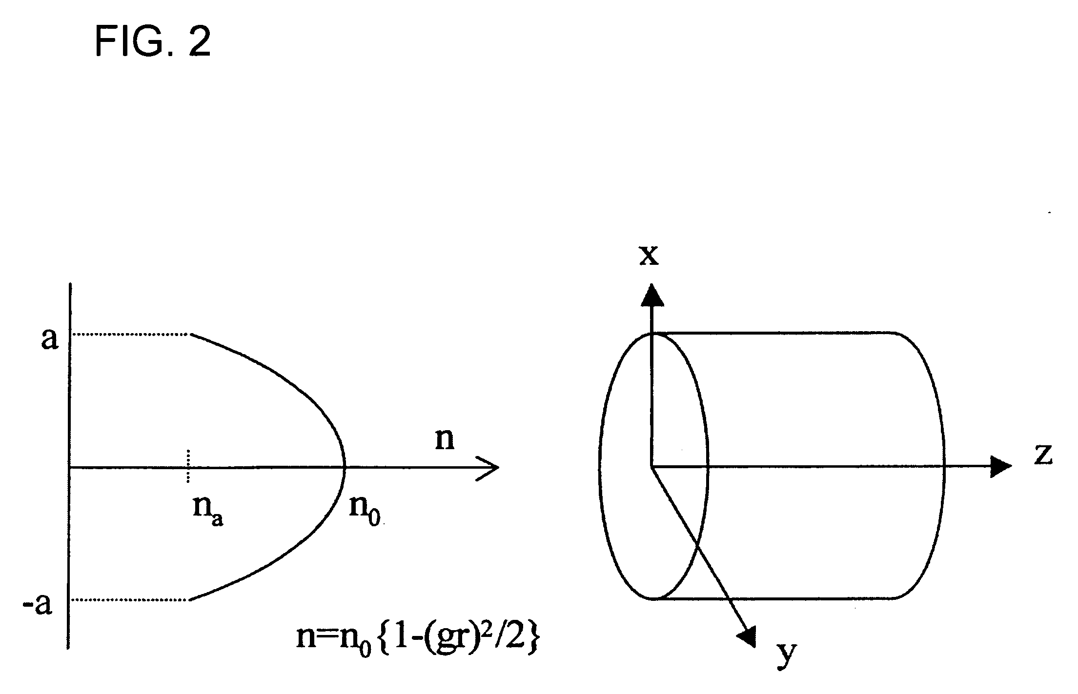
[0045]As in the case with Example 1, a prototype of the GRIN lens with NA (=0.5) which decreases in an approximately quadratic curve from the center to the periphery was obtained. The prototype was spun into an optical fiber of 166 μm in outside diameter while inserted into the electric furnace of the carbon heater at 0.04 mm / s to manufacture the GRIN lens-shaped optical fiber. The refractive index distribution of the optical fiber was determined again and resulted in a GRIN lens-shaped optical fiber with NA (=0.5) which decreases in an approximately quadratic curve from the center to the periphery, wherein the refractive index distribution constant g was 0.0042 (μm−1) when g was expressed by g=1.05 NA / n0a.

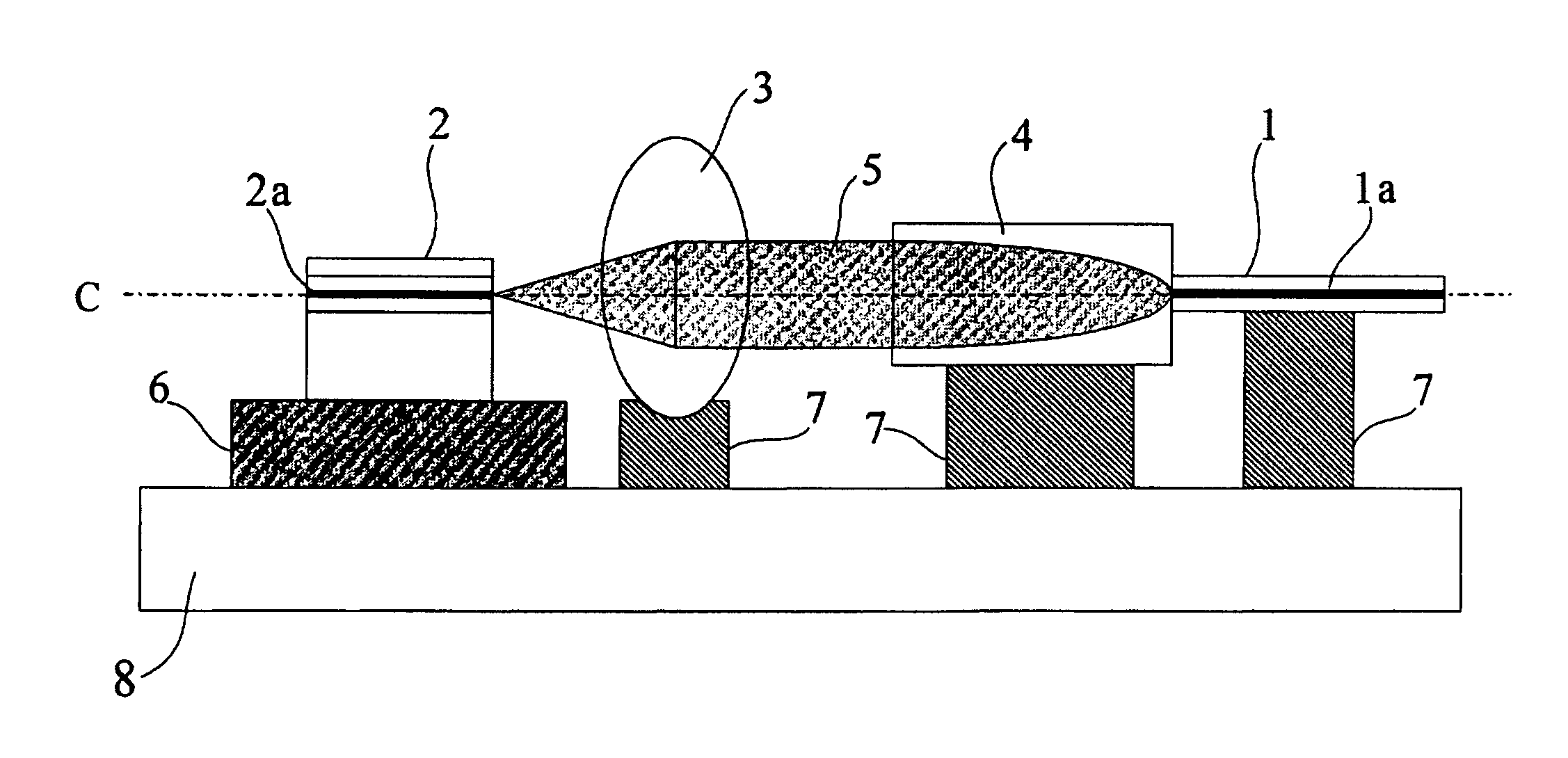
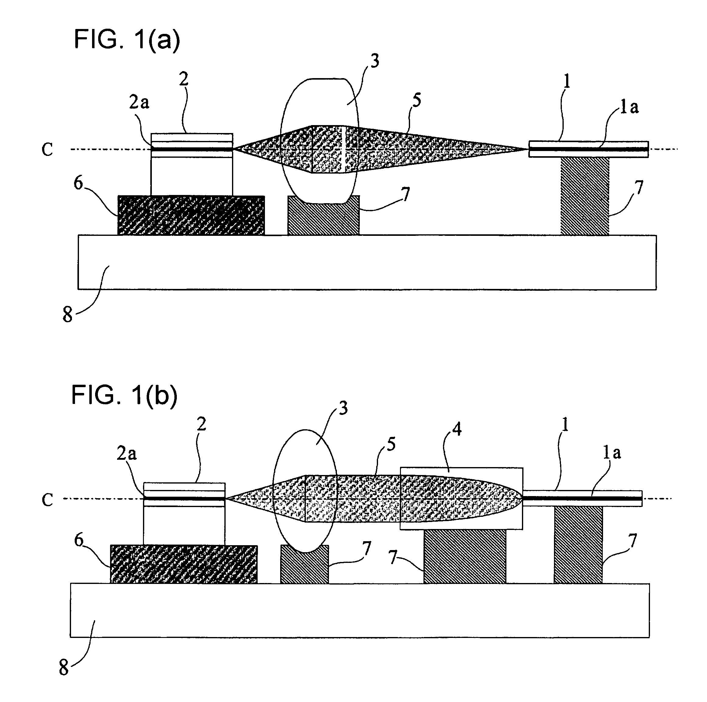
[0046]The manufactured GRIN lens-shaped optical fiber was spliced with one end of the single mode optical fiber of 0.09 in numerical aperture by fusion using the discharge fusion splicer, and then cut into the cycle length of ¼ of a zigzag cycle of a light propagated through the G...


PUM

PropertyMeasurementUnit
radiusaaaaaaaaaa
softening pointaaaaaaaaaa
diameteraaaaaaaaaa

Abstract

An optical fiber coupling part that reduces the difficulty in adjusting cores, minimizes coupling loss, and prevents optical characteristics from deteriorating. An optical fiber is fused to one end of a GRIN lens which includes a quartz glass containing one or more refractive index regulating substances selected from Sb2O3, Ta2O5, TiO2 or ZrO2. Optical characteristics are not deteriorated because an adhesive is not used, and self-alignment effects facilitate adjustment of the cores of the GRIN lens and the optical fiber. Furthemore, coupling loss can be minimized by setting a refractive index distribution constant g of the GRIN lens within an appropriate range.

Description

BACKGROUND OF THE INVENTION[0001]1. Technical Field[0002]The present invention relates to an optical fiber coupling part, namely, an optical fiber with a lens for coupling a light emitting source such as a semiconductor laser used for optical communication and an optical fiber with high coupling efficiency, and a manufacturing method thereof.[0003]2. Description of Related Art[0004]A technique for coupling a semiconductor laser and an optical fiber is one of the most important techniques in optical communication. For example, conventional methods of coupling the semiconductor laser and the optical fiber include a method using a tip ball fiber whose tip part is spherical (see U.S. Pat. No. 3,910,677), or a method using a convex lens such as a spherical lens or an aspherical lens.[0005]Since formed in small size, the method using the tip ball fiber is capable of coupling the semiconductor laser array and an optical fiber array. This tip ball optical fiber is integrally formed with a h...

Claims


Application Information

Patent Timeline
Patent Type & Authority Patents(United States)
IPC IPC(8): G02B6/32
CPCG02B3/0087G02B6/4206G02B6/30G02B6/2551
Inventor MATSUMURA, HIROYOSHISUZUKI, TAROACHIWA, TORU
Owner TOYO SEIKAN GRP HLDG LTD
Why Eureka
Try Eureka