Method and apparatus for operating a dual fuel internal combustion engine

a dual fuel internal combustion engine and fuel injection technology, applied in the direction of electrical control, process and machine control, instruments, etc., can solve the problems of increasing the pressure on the engine, increasing the capital cost of the engine and/or the operating cost, and increasing the amount of pollution. , to achieve the effect of reducing the time needed for pressur

Active Publication Date: 2009-12-01
WESTPORT FUEL SYST CANADA INC
View PDF9 Cites 219 Cited by
  • Summary
  • Abstract
  • Description
  • Claims
  • Application Information

AI Technical Summary

Benefits of technology

[0021]In a preferred apparatus, to reduce modifications to the cylinder head of conventional compression ignition engines that are fueled with a single fuel, the secondary-fuel injection valve and the main-fuel injection valve are integrated into a single assembly. The advantage of this arrangement is that a single integrated valve assembly can be installed in the same opening that is normally occupied by a single-fuel injection valve.
[0032]The method can further comprise pressurizing an accumulator vessel for the main fuel before shutting down the engine. To preserve a store of high pressure gaseous fuel inside the accumulator, the method preferably comprises closing a shut off valve between the accumulator vessel and a main fuel supply pipe before shutting down the engine. In one embodiment, the method can further comprise opening the shut off valve for a predetermined time when the engine is starting up until available injection pressure equalizes with pressure inside the accumulator, and then closing the shut off valve until the available injection pressure is raised to a high set point. The method can also further comprise pressurizing a large accumulator vessel and a small accumulator vessel, wherein both accumulator vessels are in fluid communication with a main-fuel supply pipe that delivers main fuel to the main-fuel injection valve. For example, in some systems the small accumulator can be employed to reduce the time needed to pressurize the main-fuel rail if the large accumulator is empty when the engine is starting up.

Problems solved by technology

However, a disadvantage of diesel engines is that they can produce more pollution, such as particulate matter (soot) and NOx, which are subject to increasingly stringent regulations that require such emissions to be progressively reduced over time.
However, most of these approaches add to the capital cost of the engine and / or the operating costs.
However, this feature can be viewed as a disadvantage by regulators and government agencies who offer subsidies for engines fuelled with cleaner burning gaseous fuels, because with this technology there is no easy way to ensure that an operator who applies for such a subsidy will actually fuel the subsidized engine with a gaseous fuel and engine emissions can be much higher when the engine is fuelled with only diesel fuel, compared to when the engine is fuelled with gaseous fuel and only pilot quantities of diesel fuel.
In addition, dual fuel engines that introduce fuel into the intake air manifold or intake port have been unable to match the performance and efficiency of conventional diesel engines.
Dual fuel engines that introduce the gaseous fuel into the intake air stream normally must be made with a lower compression ratio because the gaseous fuel can pre-mix with the air earlier in the compression stroke, introducing the potential for engine knock, which is the premature detonation of fuel in the combustion chamber.
A lower compression ratio results in an engine that can not match the performance and efficiency of an engine that has the same compression ratio as a diesel engine.
Another disadvantage of introducing the gaseous fuel into the intake air stream is that by occupying space in the intake air manifold, the fuel can reduce the mass of air that can flow into the combustion chamber.
However, a problem with directly injecting both fuels into the combustion chamber is that both fuels need to be supplied at a pressure that is high enough to overcome the in-cylinder pressure, while also introducing a fuel spray that penetrates into the combustion chamber space to mix with the air.
However, because a gaseous fuel is a compressible fluid, there can be times during operation of the engine when it is not possible to supply the gaseous fuel at the desired injection pressure.
For example, this can occur when the engine is starting up, or when the gaseous fuel tank is empty, or if there is a problem with the gaseous fuel pump or compressor.
In start-up conditions, when the gaseous-fuel supply system is being pressurized, opening the gaseous-fuel injection valve can slow the time it takes to raise gaseous fuel pressure to the normal operating level.
Failing to recognize that gaseous-fuel is not being introduced into the combustion chamber with the desired injection pressure or in the desired amounts can result in poor combustion, higher particulate matter and unburned hydrocarbon exhaust emissions, and lower engine performance and efficiency, since injection timing may not be matched to the amount of fuel being introduced into the combustion chamber.
For some engines that use a gaseous fuel as the main fuel, the liquid fuel injection valves are not capable of introducing enough liquid fuel to operate the engine at full power using liquid fuel alone.
For example, if the nozzle orifices are sized for delivering smaller quantities of liquid fuel with predetermined flow rates and velocities under normal operating conditions such orifices may be sized too small to introduce liquid fuel in quantities sufficient to operate the engine on only liquid fuel.

Method used


Image

  • Method and apparatus for operating a dual fuel internal combustion engine
  • Method and apparatus for operating a dual fuel internal combustion engine
  • Method and apparatus for operating a dual fuel internal combustion engine

Examples


Embodiment Construction

)

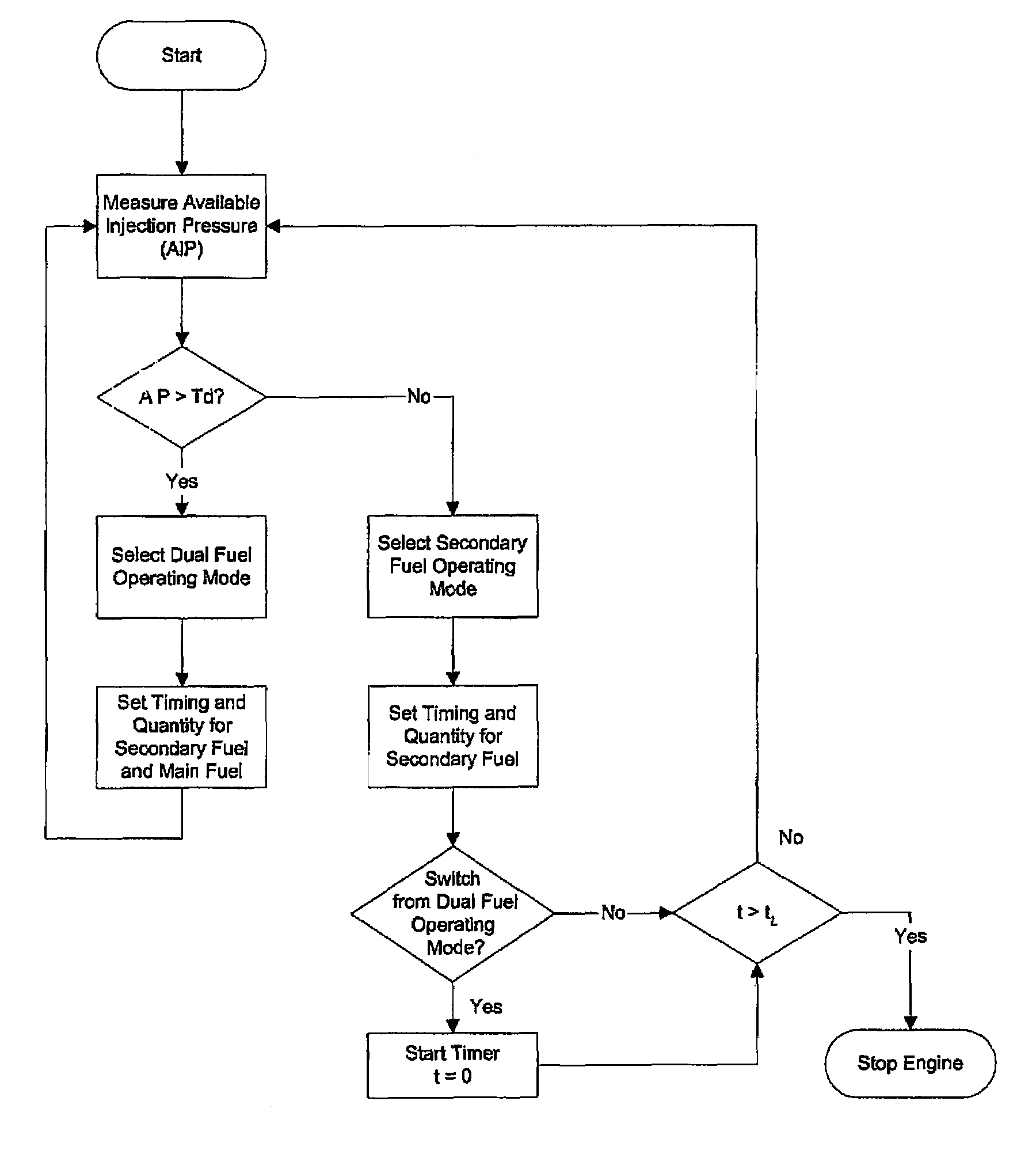
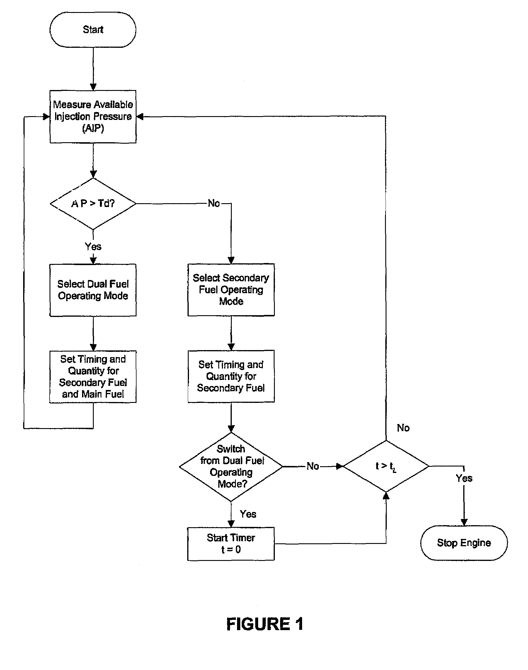
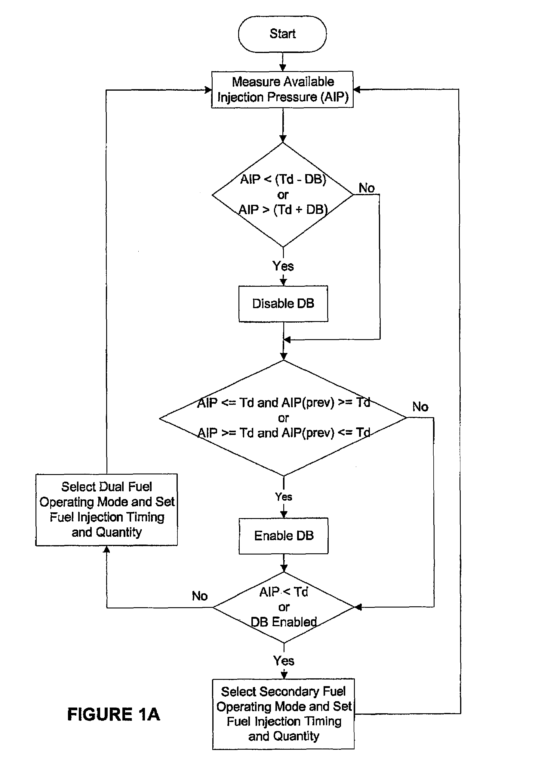
[0036]The present method is directed to internal combustion engines that are fuelled with a main fuel and a secondary fuel wherein the two fuels can be independently and separately introduced directly into the engine's combustion chamber. In some embodiments, the secondary fuel injection valve is adapted to introduce smaller quantities of fuel on an energy basis. For such engines, a control strategy is needed to handle the situation when the main fuel is unavailable. This is especially true for engines that have secondary-fuel injection valves with a geometry that restricts secondary fuel mass flow rate to the extent that the engine is unable to operate at full power with secondary fuel alone.

[0037]In this disclosure, “secondary fuel” is a term that is used to describe a second fuel that is normally more auto-ignitable than the main fuel. Under normal operation, only a small quantity of secondary fuel is injected into the combustion chamber to assist with ignition of the main fuel....


PUM


Abstract

In an internal combustion engine that can burn two fuels, the main fuel may become unavailable, either temporarily or until the main fuel is replenished. The present apparatus determines when to fuel an engine with main fuel and secondary fuel, or secondary fuel alone. The apparatus includes a main-fuel supply system comprising a main-fuel injection valve that introduces main fuel into an engine combustion chamber; a secondary-fuel injection system comprising a secondary-fuel injection valve that introduces secondary fuel directly into the combustion chamber; a pressure sensor associated with the main-fuel supply system for determining injection pressure inside the main-fuel injection valve; and an electronic controller in communication with the pressure sensor and programmable to separately command actuation of the secondary-fuel and the main-fuel injection valve when injection pressure is greater than a predetermined threshold, and to otherwise command actuation of the secondary-fuel injection valve and not the main-fuel injection valve.

Description

CROSS-REFERENCE TO RELATED APPLICATION(S)[0001]This application is a continuation of International Application No. PCT / CA2007 / 000401, having an international filing date of Mar. 9, 2007, entitled “Method And Apparatus For Operating A Dual Fuel Internal Combustion Engine”. The '401 international application claimed priority benefits, in turn, from Canadian Patent Application No. 2,538,980 filed Mar. 10, 2006. The '401 international application is hereby incorporated by reference herein in its entirety.FIELD OF THE INVENTION[0002]The present invention relates to a method and apparatus for operating a dual fuel internal combustion engine. More specifically, the invention relates to a method and apparatus for an electronic engine controller to automatically determine when to deliver two fuels or only one fuel to the engine's combustion chamber.BACKGROUND OF THE INVENTION[0003]Engines that burn diesel fuel are the most popular type of compression ignition engines. So-called diesel engine...

Claims


Application Information

Patent Timeline
Patent Type & Authority Patents(United States)
IPC IPC(8): F02D19/08F02D41/30
CPCF02D19/027F02D19/105F02M21/0224F02D19/0694Y02T10/36Y02T10/32F02M21/0287Y02T10/30
Inventor BATENBURG, GREGTHOMPSON, JEFFCHAMBERS, DOUGLAS
Owner WESTPORT FUEL SYST CANADA INC
Why Eureka
Try Eureka