
Solid oxide fuel cell positive electrode-electrolyte-negative electrode

a technology of solid oxide fuel cells and positive electrodes, applied in the direction of fuel cells, fuel cell auxilaries, electrical equipment, etc., can solve the problems of difficult to meet the requirements of the application of the material, the interconnection plate is difficult to produce, and the cost of the interconnection plate is an obstacle to the profitability of the electrical energy produced by this type of device, etc., to improve the catalytic power and thermal expansion coefficient and conductivity of the anode layer, improve the tolerance of the so

Active Publication Date: 2009-12-15
HTCERAMIX
View PDF17 Cites 24 Cited by
  • Summary
  • Abstract
  • Description
  • Claims
  • Application Information

AI Technical Summary

Benefits of technology

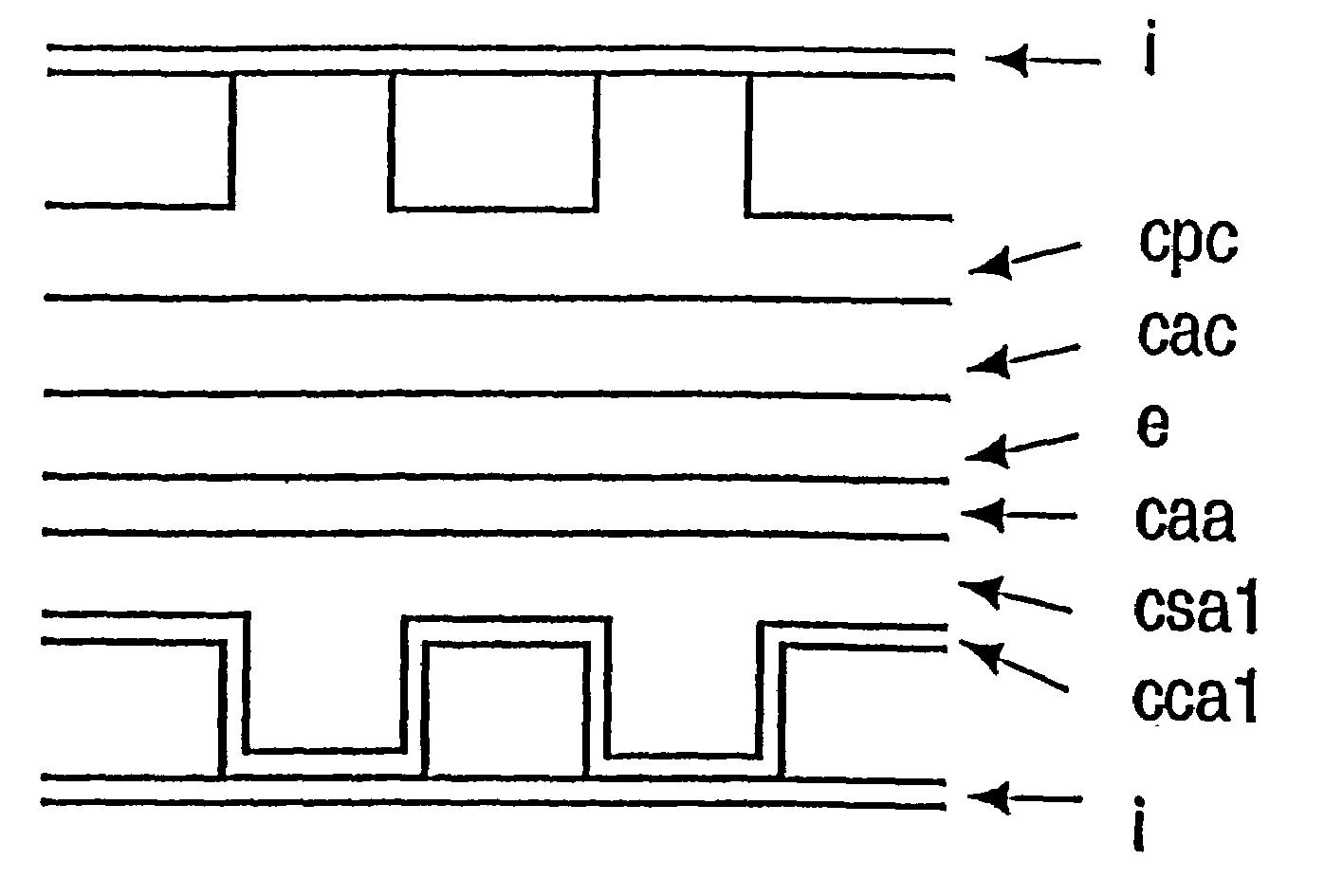
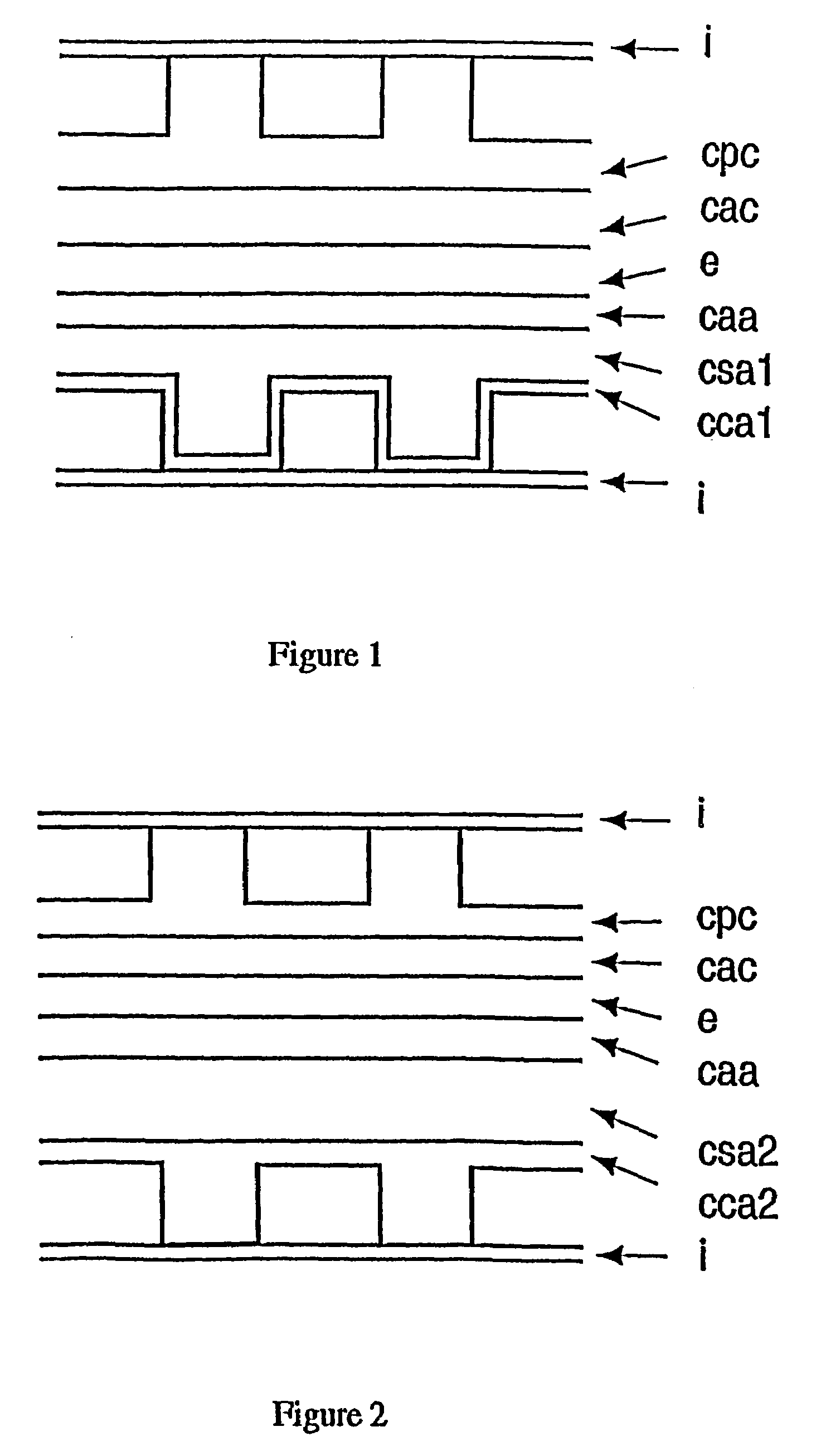
[0017]A PEN according to the invention therefore allows the use of an interconnecting plate which is formed by a simple plate which is planar and smooth on the anode side. Moreover, since the mechanical support of the PEN is formed by the anode support layer, during assembly of the electrolyte between the two electrodes it is possible to reduce this electrolyte to a thin layer of a few μm, having a low ohmic resistance.
[0053]In order to improve the tolerance to sulfur, it is possible to add cerium dioxide, CeO2, to the catalysts in a proportion of from 5 to 100% by weight with respect to the Ni-based catalysts, preferably 10 to 50% and in particular from 15 to 25% by weight. The presence of Cu at the anode also improves the tolerance to sulfur.

Problems solved by technology

A stack comprises about 70 cells and has a height of about 50 cm; the electrical power produced is 1 kW under 40 V. The interconnecting plates of this type of stack are complicated to produce and are expensive.
The power and electrical voltage delivered by this device are a function respectively of the surface area and the number of cells, and hence of the surface area and number of interconnecting plates, the cost of which forms an obstacle to the profitability of the electrical energy produced by this type of device.
These elements, which are almost completely hollow, are fragile and it is difficult to seal between the electrodes and these elements.
The structure forming the channels is sintered on the electrolyte, which means that it is not possible to compensate the planarity defects of the cell.
However, this PEN requires interconnecting plates with a complex structure comprising the supply and evacuation tubes for the gases, and are thus quite thick, in order to form a stack.
This structure is therefore disadvantageous on account of its thickness and the cost of the interconnecting plates.
However, the column structure is complicated to produce, and handling of the components of the cell during assembly is delicate.
However, handling of the electrolyte plate (0.2 to 0.4 mm thick) during stacking is delicate.
This variant is expensive to implement, as in the case of the Sulzer interconnecting plates described above.

Method used


Image

  • Solid oxide fuel cell positive electrode-electrolyte-negative electrode
  • Solid oxide fuel cell positive electrode-electrolyte-negative electrode
  • Solid oxide fuel cell positive electrode-electrolyte-negative electrode

Examples


example 1

Production of a Mold for Gas Channels

[0100]In a first step, a “master” mold is produced which represents as positive the gas distribution channels. This master mold may be produced by micromachining a metal part, for example by means of electroerosion. It may also be produced by a stereolithography process or by a UV LIGA process, these processes being known in the prior art.

[0101]In a second step, a liquid rubber (RTV-ME 622, Wacker Silicone) is cast into the master mold. Following polymerization of the rubber, the latter is removed from the master mold. A flexible, negative mold for the gas distribution channels is thus obtained.

example 2

Production of a Structured Anode Collector Layer, by Polymerization

[0102]The layer is formed using zirconia particles (8 YSZ) and nickel oxide particles (60 to 100% with respect to the weight of the zirconia), having a diameter of between 0.2 and 1.5 μm.

[0103]The ceramic powders which are intended to form the anode support layer are dispersed in water with the aid of a polyelectrolyte dispersant (Duramax D3005, Rohm and Haas Company). A difunctional acrylate monomer (SR 610, Sartomer, USA) is added to the dispersion, in a proportion of 8 to 15% by weight with respect to the ceramic powders. Just before the dispersion is placed in the mold, a polymerization reaction initiator is added, for example ammonium persulfate and tetramethylenediamine, each in an amount of 0.5% by weight with respect to the weight of the acrylate monomer. The dispersion is placed in the rubber mold, degassed, and the mold is pressed against a smooth anode support layer which has been obtained beforehand by st...

example 3

Production of a Gas Distribution Structure (Variant)

[0104]The process is the same as in Example 2. The polymerization initiator is diethylenetriamine, in an amount of 5% by weight with respect to the monomer.


PUM


Abstract

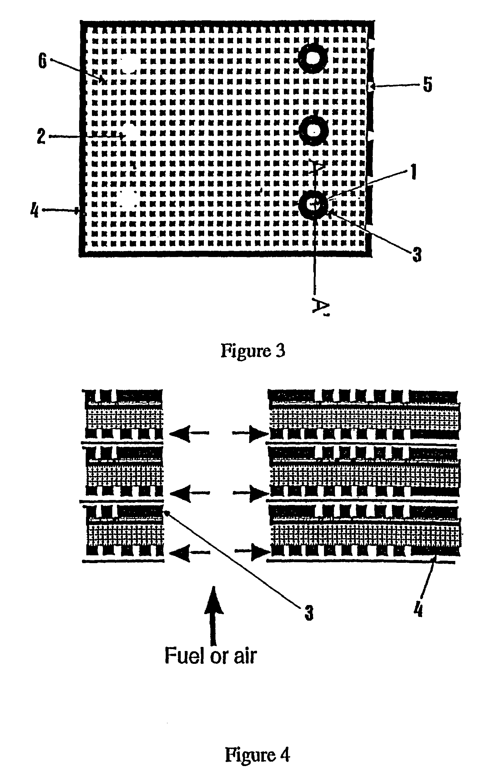
Disclosed is a solid oxide fuel cell (SOFC) positive electrolyte negative (PEN) comprising electrodes on the rear side thereof used for establishing contact between a flat interconnecting plate and a raised structure which is configured in such a way that it forms gas circulation channels with said plate. The PEN and interconnecting plates can have holes so as to create internal gas inlet and outlet tubes. The electrolyte / electrode interface can also be configured as a raised structure increasing the ratio of the extended area to the projected area.

Description

FIELD OF THE INVENTION[0001]The present invention relates to the field of solid oxide fuel cells which are commonly referred to as SOFCs.BACKGROUND OF THE INVENTION AND PRIOR ART[0002]A fuel cell has an anode and a cathode which are separated by an electrolyte that transports the ions but does not conduct the electrons. The cathode-electrolyte-anode assembly is commonly referred to as a PEN (Positive electrode-Electrolyte-Negative electrode). The electrolyte consists of a metal oxide in solid, non-porous form, for example a zirconium oxide, which is capable of transporting oxygen anions. The anode, which is porous, is the place where a gaseous fuel, generally hydrogen, or even an organic fuel (methanol, light fuel, natural gas) with the hydrogen being extracted therefrom by reforming, undergoes an oxidation reaction. The oxygen of the air undergoes a reduction reaction at the cathode, which is porous. The reaction is continuous by virtue of the continuous supply of fuel gases and ox...

Claims


Application Information

Patent Timeline
IPC IPC(8): H01M4/86H01M4/90H01M8/12H01M4/88H01M8/02H01M8/24
CPCH01M8/1206H01M8/2425H01M8/1213Y02E60/525Y02E60/521H01M8/1231Y02E60/50H01M8/2483H01M8/2432H01M8/12H01M8/24H01M4/86
Inventor IHRINGER, RAPHAELCLOSSET, ALEXANDRESFEIR, JOSEPHBUCHELI, OLIVIER FRANZ
Owner HTCERAMIX
Learn More