
UV cure equipment with combined light path

a technology of ultraviolet light and cure equipment, which is applied in the direction of optical radiation measurement, spectrometry/spectrophotometry/monochromator, nuclear engineering, etc. it can solve the problems of not disclosing the method of photo-curing the ink on the heat-sensitive substrate, the drying process of opaque conductive inks requires many minutes to cure the ink, and the inability to modify information, etc., to achieve rapid and complete polymerization, rapid and complete curing

Inactive Publication Date: 2009-12-29
EASTMAN KODAK CO
View PDF40 Cites 60 Cited by
  • Summary
  • Abstract
  • Description
  • Claims
  • Application Information

AI Technical Summary

Benefits of technology

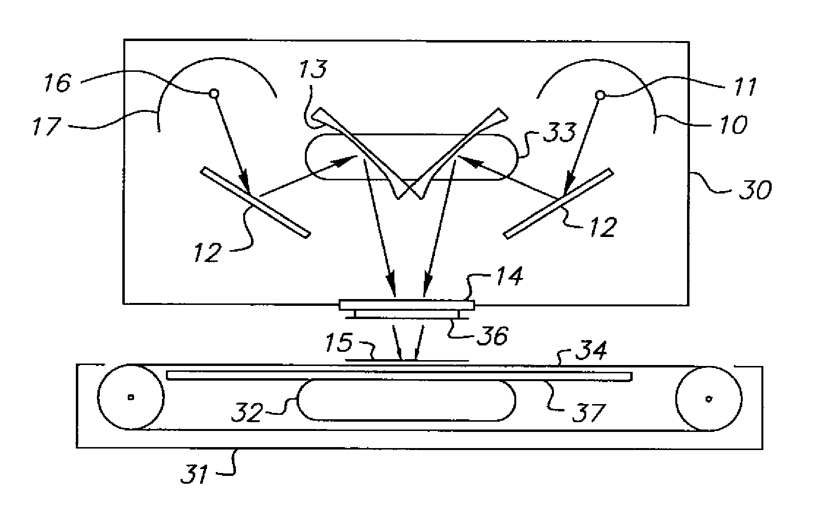
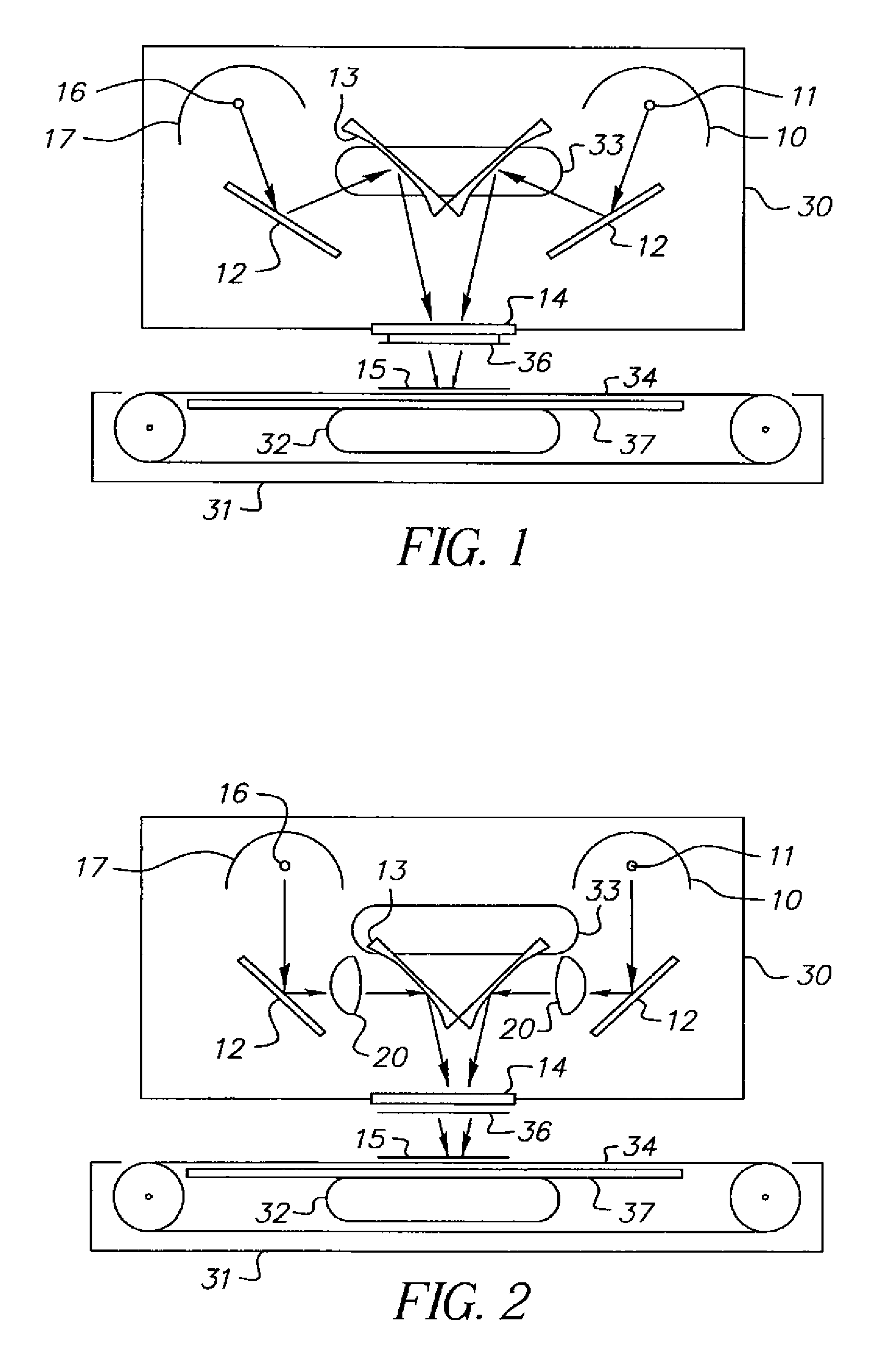
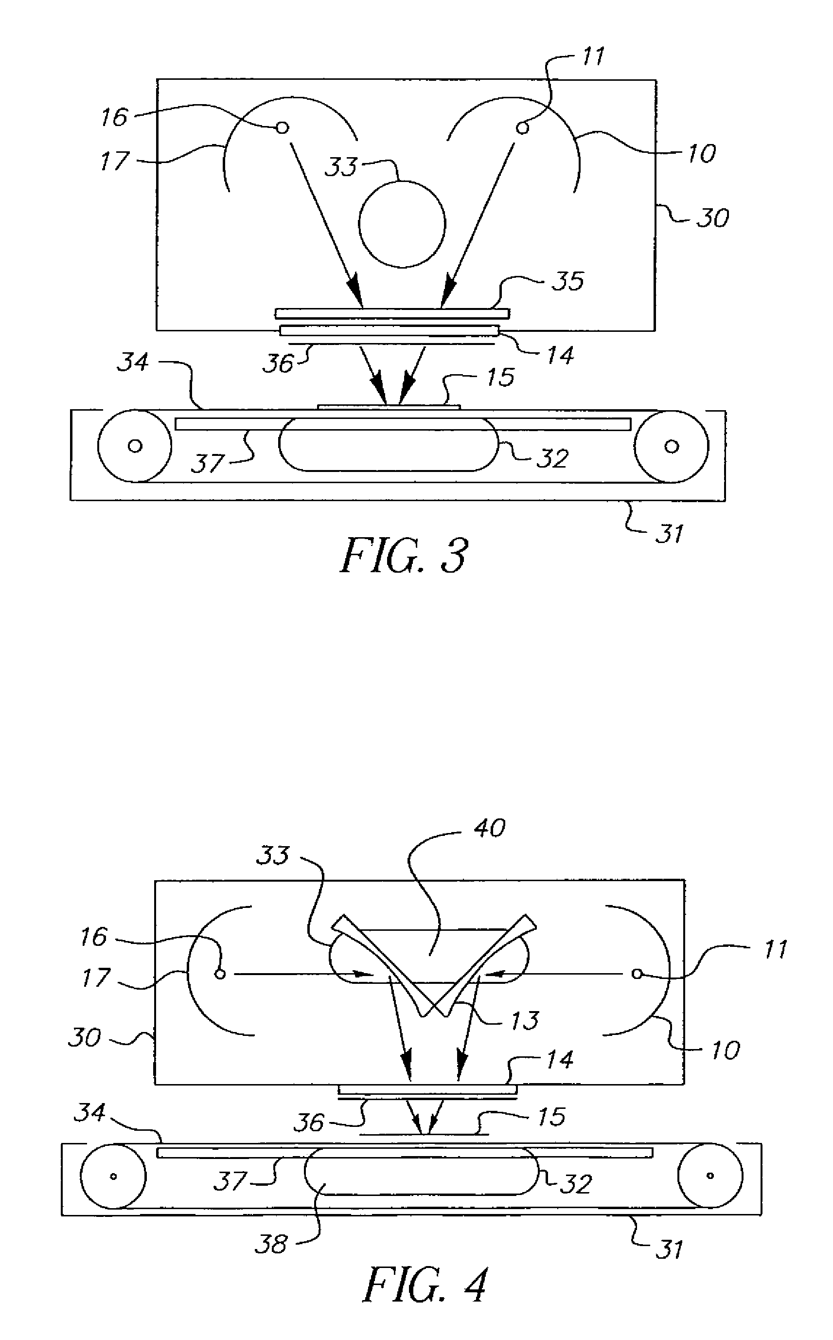
The present invention is about a curing assembly that has two or more light sources that have different colors. These light sources are combined to create a single light path that can cure materials that are exposed to it. The technical effect of this invention is that it provides a more efficient and effective way to cure materials using multiple light sources that have different colors.

Problems solved by technology

Devices that allow for the modification of information, such as electrically updated displays, are often heavy and expensive.
The drying process for opaque conductive inks requires many minutes to cure the ink.
However, this material is not disclosed for use in display devices, nor does it disclose methods to photo-cure the ink in display devices or on heat sensitive substrates.
However, this patent does not disclose use for display devices, such as a flexible display containing material that is heat sensitive.
Further, there is no mechanism for eliminating or removing the IR component of the spectrum of light emitted that is absorbed by the target UV curable material.
Experiments with single bulb UV cure configurations, for curing a UV sensitive silver bearing ink such as Allied Photochemical UVAG 0010©, have shown that a single bulb configuration does not produce an adequate cure that enables a roll-to-roll manufacturing process.
When illuminating UV curable ink on opaque surfaces, such as on a PDLC coating containing a light absorbing layer between the PDLC and photo-curable ink, the ink does not fully cure to the extent that it can be wound up in a roll-to-roll manufacturing process, causing some ink transfer to the backside of sequentially wrapped layers.
Insufficient exposure of the curable material results in insufficient cure, producing low resistivity, in the case of conductive materials, and blocking, that is, transfer of the curable material between rolls when the rolls are wound after processing.
Commercially available UV curing equipment, consisting of a model LC-6B conveyor assembly and two F300S UV curing lamp assemblies is shown in FIG. 5, enable a rapid cure of the silver bearing photo initiator ink in a panelized process, but is not conducive to a roll-to-roll process.
One disadvantage of this type system is that it also creates high levels of heat in the form of IR waves and hot air from the cooling of the lamps, which can be detrimental to heat sensitive substrates.
Exposing an IR spectra onto a PDLC surface can cause thermal transition of the PDLC layer, and can also cause thermal-induced damage to the flexible substrate as well.
In addition, the Fusion lamps are positioned at a distance from each other and illuminate different areas of the curable material, which results in non-uniform cure of material.
In the case of small articles, the system is unable to expose the small areas to exposure by both light sources in a single pass, resulting in increased manufacturing complexity.
This situation will result in significant and possibly unacceptable curing variability.
However, this invention does not disclose use in a UV curing chamber for curing photosensitive inks, nor does it disclose how the IR spectrum could be minimized to avoid thermal transition of a heat sensitive substrate.

Method used


Image

  • UV cure equipment with combined light path
  • UV cure equipment with combined light path
  • UV cure equipment with combined light path

Examples


example 1

[0110]Samples of Plain PET, Merck BL118 only, Merck BL 118 over coated with either a Black or Blue contrast layer were screen printed with EXGHAAMJ-AG conductive UV curable ink from Allied Photochemical. The samples were then cured using a Dual lamp fusion UV unit and conveyor system and tested for resistivity.

Black Nano and LC Coated Samples Composition

[0111]An aqueous coating dispersion layer of the chiral nematic composition was prepared containing 5 wt % gelatin, 8 wt % droplets of Merck BL118 obtained from Merck, Darmstadt, Germany and 0.20 wt % of coating surfactant. Microscopic analysis showed that the dispersion consisted of uniform 8 micron droplets of the liquid crystal in an aqueous gelatin medium. A second coating solution was prepared with 4 wt % gelatin and a mixture of nanopigments milled to less than 1 micron in size was formulated to provide a neutral black density. The two layers were coated and together had a resulting dried thickness of 14 microns.

Blue Nano and L...

example 2

Black Nano and LC Coated Samples Composition

[0119]An aqueous coating dispersion layer of the chiral nematic composition was prepared containing 5 wt % gelatin, 8 wt % droplets of Merck BL118 obtained from Merck, Darmstadt, Germany and 0.20 wt % of coating surfactant. Microscopic analysis showed that the dispersion consisted of uniform 8 micron droplets of the liquid crystal in an aqueous gelatin medium. The solution was mixed with gelatin crosslinker bisvinylsulfonylmethane at 3 wt % relative to the total amount of gelatin immediately before coating.

[0120]A second coating solution was prepared with 4 wt % gelatin and a mixture of nanopigments milled to less than 1 micron in size was formulated to provide a neutral black density (CMYK) layer. The two layers were coated and together had a resulting dried thickness of 14 microns.

Carbon Black Nano and LC Coated Samples Composition

[0121]An aqueous coating dispersion layer of the chiral nematic composition was prepared containing 5 wt % g...

example 3

[0131]The samples utilized above in Example 2 were also evaluated for thermal sensitivity. Once samples were printed and cured, the thermal transition of the coating was evaluated to determine the impact of the quartz and IR filters on the elimination / reduction of thermal transition (without impacting resistivity). The thermal transition was evaluated by visually looking at each sample to identify the existence of thermally transitioned liquid crystal.

[0132]

TABLE 3QuartzHeat Sink / ThermalSample #Coating typeLamp: S* or D**plusExchangertransition3-1BL 118Snonenone33-2BL 118Dnonenone33-3BL 118D+1Rnone33-6BL 118D+2Rnone33-6BBL 118Dnoneyes33-9BL118 with CMYKSnonenone33-10BL118 with CMYKDnonenone13-11BL118 with CMYK &D+1Rnone1hardener3-13BL118 with CB &D+1Rnone1hardener3-15BL118 with CMYKD+1Rnone13-18BL118 with CMYK &D+2Rnone1hardener3-20BL118 with CB &D+2Rnone1hardener3-22BL118 with CMYKD+2Rnone13-22BBL118 with CMYKDnoneyes33-23BBL118 with CB &Dnoneyes3hardener3-25575 nm LC with CMSnonen...


PUM

PropertyMeasurementUnit
thicknessaaaaaaaaaa
thicknessaaaaaaaaaa
diameteraaaaaaaaaa

Abstract

The present invention relates to a curing assembly comprising at least two light sources combined into one light path, wherein the light sources are capable of curing a material exposed to the combined light path. The invention also relates to a method of curing a material or material in contact with a heat sensitive material comprising providing a curable material or a material associated with a heat sensitive material and exposing curable material to a combined light path from the curing assembly.

Description

FIELD OF THE INVENTION[0001]The present invention relates to roll-to-roll processing of ultraviolet (UV) curable materials in flexible displays. In particular, the invention can be utilized in manufacturing polymer dispersed chiral nematic liquid crystal displays on flexible or heat sensitive substrates. The present invention also relates to the equipment to cure UV initiated materials, especially polymers, used in the roll-to-roll manufacture of flexible displays. In particular, the invention can be used for curing ultraviolet (UV) sensitive inks used in the fabrication of liquid crystal displays on flexible or heat sensitive substrates.BACKGROUND OF THE INVENTION[0002]Currently, information is displayed using assembled sheets of paper carrying permanent inks or displayed on electronically modulated surfaces such as cathode ray displays or liquid crystal displays. Printed information displayed in these manners cannot be changed. Devices that allow for the modification of informatio...

Claims


Application Information

Patent Timeline
Patent Type & Authority Patents(United States)
IPC IPC(8): H01J37/00
CPCF26B3/28
Inventor KILBURN, JOHN I.MCCOLLOUGH, GEORGE T.COLEMAN, RUSTY J.CAPRIO, CRAIG A.KIRCHER, JAMES R.SLATER, DANIEL A.
Owner EASTMAN KODAK CO
Learn More