Laser beam scanning device, image forming apparatus, and laser beam detecting method by the laser beam scanning device

a laser beam scanning and laser beam technology, applied in the field of image forming apparatus, laser beam detecting methods by laser beam scanning devices, can solve the problems of increasing color registration, increasing the cost of detection, so as to achieve accurate detection of position, low cost, and low cost

Inactive Publication Date: 2010-01-05
RICOH KK
View PDF17 Cites 11 Cited by
  • Summary
  • Abstract
  • Description
  • Claims
  • Application Information

AI Technical Summary

Benefits of technology

[0034]According to an embodiment of the present invention, in a laser beam scanning device, a laser beam output from a light source is deflected by a laser beam deflecting unit and the deflected laser beam is condensed on a surface to be scanned by a scanning optical system. The laser beam which is led to the surface to be scanned is input to a diffraction optical element and the diffraction optical element forms a pattern of a diffraction image. The pattern of the diffraction image includes plural images where intervals therebetween are different in a first direction corresponding to the main scanning direction at a position in a second direction corresponding to the sub scanning direction at least at a part of the plural images. Then, a light detector detects the pattern of the diffraction image. The detected result by the light detector includes position information of the input laser beam in the second direction. Consequently, the laser beam scanning device can accurately detect the position of a light spot to be formed on the surface to be scanned without high cost and without a large size.
[0035]According to an embodiment of the present invention, when it is defined that the width in a diffraction angle distribution in the first direction is θmax, an interval between pixels of the diffraction optical element is “p”, a using wavelength is λ, and λ>“p”, the interval “p” is determined by satisfying the following inequality: arcsin(λ / p)>θmax. Therefore, a diffraction image by a high-order laser beam does not overlap a diffraction image by a first-order laser beam. Consequently, the laser beam scanning device can accurately detect the position of a light spot to be formed on the surface to be scanned.
[0036]According to an embodiment of the present invention, since the size of the laser beam scanning device is small, when the laser beam scanning device is installed in an image forming apparatus, the image forming apparatus can be designed without any restriction of the layout.
[0037]According to an embodiment of the present invention, since a general-purpose photodiode or a general-purpose photo IC can be used as the light detector, the laser beam scanning device can be formed with low cost.

Problems solved by technology

However, the out of color registration may be increased with the passage of time after delivering the apparatus.
Especially, when a resin condenser lens is used, since the thermal expansion coefficient of the resin condenser lens is large, the positional change of the scanning laser beam becomes large due to the temperature change.
However, when printing is continuously executed, the scanning positional shift is increased by heat from a fixing unit and a polygon mirror motor; therefore, when the number of printing cycles of one job is large, the out of color registration is gradually increased.
However, in Patent Documents 5 and 6, when a positional shift amount of laser beams is detected by using a special-shaped light receiving element; the size of the light receiving element becomes large and the shape thereof becomes complex.
Consequently, the layout of the apparatus becomes complex and the apparatus becomes large and these result in a cost increase.
However, in Patent Documents 3 and 4, when the special photodiodes are used, the cost is increased.
That is, a region where a light deflector can scan must be large; as a result, the scanning optical system becomes large.
Consequently, it becomes difficult to manufacture the apparatus due to an increase of a sensitivity error and a large thickness of a scanning lens.
That is, it is difficult to miniaturize the apparatus.
The exclusive special photo IC includes a light receiving element and a comparator circuit; this causes high cost.
Therefore, when the exclusive special photo IC is used, optical characteristics (fθ characteristics) of the scanning laser beams in the detecting region become largely different from those in the image forming region; consequently, detecting accuracy becomes low.
In addition, when the general-purpose low-cost photo IC is used, detection accuracy is degraded caused by various factors relating to a change of the light receiving amount.

Method used


Image

  • Laser beam scanning device, image forming apparatus, and laser beam detecting method by the laser beam scanning device
  • Laser beam scanning device, image forming apparatus, and laser beam detecting method by the laser beam scanning device
  • Laser beam scanning device, image forming apparatus, and laser beam detecting method by the laser beam scanning device

Examples


first embodiment

[0094]First, referring to the drawings, a first embodiment of the present invention is described.

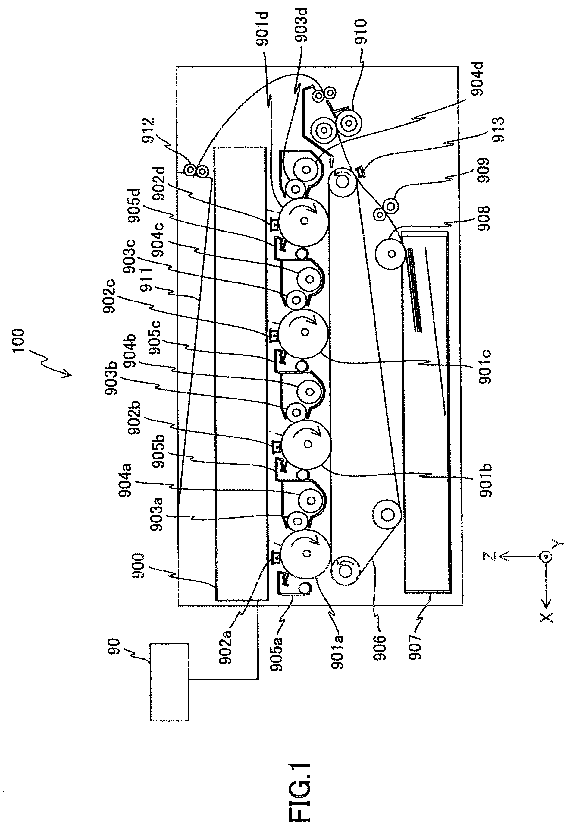
[0095]FIG. 1 is a schematic diagram showing an image forming apparatus according to the first embodiment of the present invention. In FIG. 1, as the image forming apparatus, a full color image forming apparatus 100 is used.

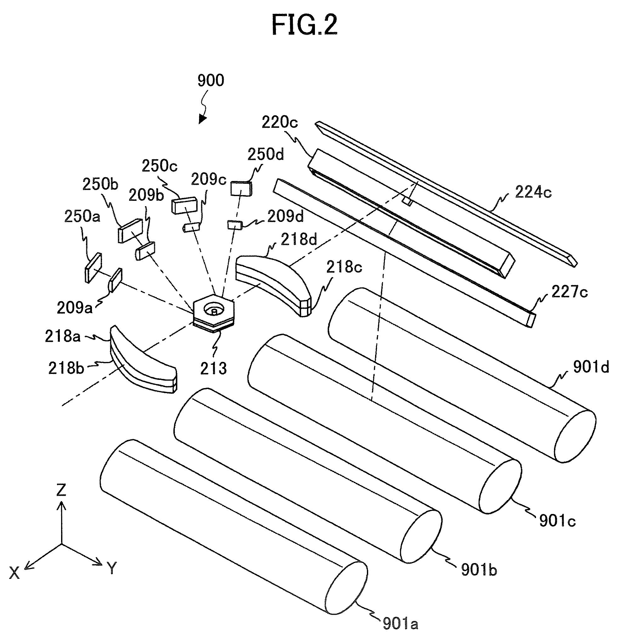
[0096]The full color image forming apparatus 100 forms a color image by superposing four color images of yellow, magenta, cyan, and black. The full color image forming apparatus 100 includes a laser beam scanning device 900, four photoconductor drums 901a, 901b, 901c, and 901d, four drum chargers 902a, 902b, 902c, and 902d, four developing rollers 903a, 903b, 903c, and 903d, four toner cartridges 904a, 904b, 904c, and 904d, four cleaning units 905a, 905b, 905c, and 905d, a transfer belt 906, a paper feeding tray 907, a paper feeding roller 908, a pair of registration rollers 909, a transfer charger 913, fixing rollers 910, a paper outputting tray 911, and paper outputt...

first modified example of first embodiment

[0192]Next, a first modified example of the first embodiment of the present invention is described.

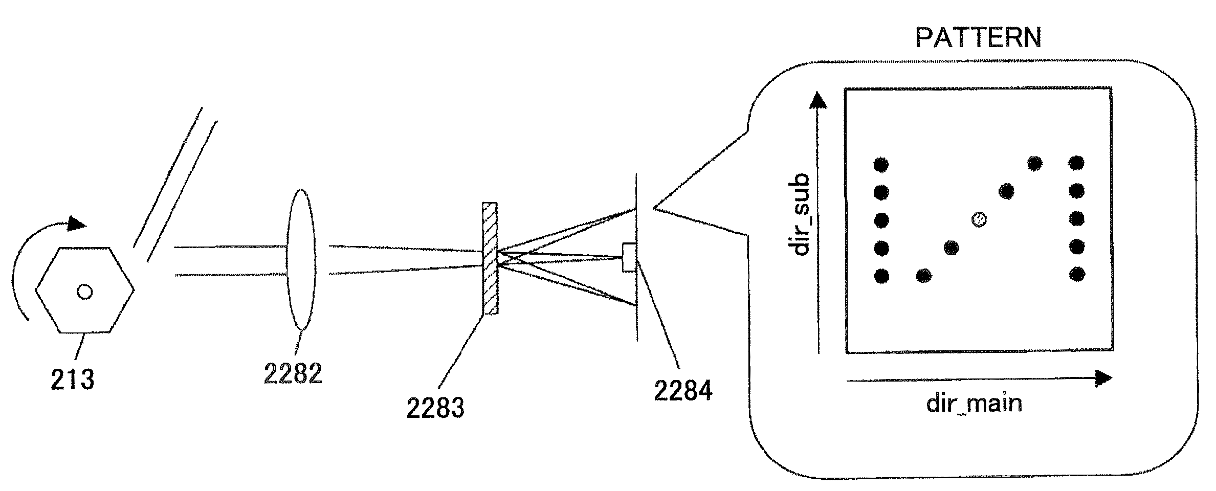
[0193]In the first embodiment, the position shift of the light spot to be formed on the surface of the photoconductor drum 901 is corrected by adjusting the image forming start position in the sub scanning direction; however, the correction method is not limited to the above. FIG. 22 is a perspective view of a mechanism using a wedge-shaped prism in the first modified example of the first embodiment of the present invention. For example, as shown in FIG. 22, when it is necessary to shift the position less than one line, a wedge-shaped prism 501 can be disposed between the light source unit 250 and the polygon mirror 213. The wedge-shaped prism 501 has a light input surface and a light output surface non-parallel to the light input surface and is rotated around the optical axis 504 by a rotating mechanism (not Shown). The wedge-shaped prism 501 outputs an output laser beam 503 deflected...

second modified example of first embodiment

[0194]Next, a second modified example of the first embodiment of the present invention is described.

[0195]FIG. 23 is a diagram showing a liquid crystal deflection element for correcting the position shift of the light spot on the surface of the photoconductor drum 901. As shown in FIG. 23, a liquid crystal deflection element 143 can be used to correct the position shift of the light spot on the surface of the photoconductor drum 901 in the sub scanning direction. The liquid crystal deflection element 143 deflects light by utilizing characteristics that the refractive index for light having a deflection direction is changed by applying a voltage. The liquid crystal deflection element 143 is disposed between the light source unit 250 and the polygon mirror 213, similar to the wedge-shaped prism 501.

[0196]FIG. 23(a) shows the shape of the liquid crystal deflection element 143 and an effective area EA where the optical path of the laser beam can be deflected is disposed in the center of...


PUM


Abstract

A laser beam scanning device is disclosed. The laser beam scanning device includes a diffraction optical element which forms a pattern of a diffraction image including two images extending in a direction corresponding to the sub scanning direction and one image extending in a direction inclined by θ (0<θ<90°) from the direction corresponding to the sub scanning direction by inputting a laser beam which is led to a surface of a photoconductor drum, and a light receiving element which receives the pattern of the diffraction image.

Description

BACKGROUND OF THE INVENTION[0001]1. Field of the Invention[0002]The present invention generally relates to a laser beam scanning device which scans a surface to be scanned by a laser beam emitted from a light source, an image forming apparatus using the laser beam scanning device, and a laser beam detecting method by the laser beam scanning device.[0003]2. Description of the Related Art[0004]Recently, in an image forming apparatus of an electrophotographic system which is applied to a laser printer, a laser plotter, a laser facsimile apparatus, a digital copying apparatus, and so on, a color image is formed, and a high quality is required for the color image. In order to achieve the high quality of the color image, out of color registration must be decreased. The out of color registration can be decreased by applying several adjusting processes to the apparatus when the image forming apparatus is delivered from a factory to a customer. However, the out of color registration may be i...

Claims


Application Information

Patent Timeline
Patent Type & Authority Patents(United States)
IPC IPC(8): B41J2/435B41J2/47
CPCB41J2/471G02B26/0808G02B26/123
Inventor IMAI, SHIGEAKISUZUKI, MITSUO
Owner RICOH KK
Why Eureka
Try Eureka