
Integrated nanomechanical sensor array chips

a sensor array and nanomechanical technology, applied in the field of heterogeneous integration of sensor arrays, can solve the problems of unacceptably high non-specific binding of snps, limited utility in certain applications, and commercial maturation

Inactive Publication Date: 2010-02-02
PENN STATE RES FOUND
View PDF8 Cites 10 Cited by
  • Summary
  • Abstract
  • Description
  • Claims
  • Application Information

AI Technical Summary

Problems solved by technology

It is also unlikely that extensions to this technique will provide quantitative data regarding the concentration of particular DNA sequences, especially for extremely low concentrations of DNA.
Finally, because nonspecific binding of SNPs is unacceptably high even with short oligonucleotides, further refinements are needed before gene variations can be thoroughly studied using these biosensor arrays.
There are several other techniques that also rely on fluorescent tagging and / or optical readout, which have not matured commercially to the level of the “gene chip”.
However, each of these techniques still requires sophisticated optical detection, which may limit their utility in certain applications.
While it is difficult to scale and integrate QCM technology, two groups have investigated a related approach that uses silicon micromachined cantilevers as strain- or mass-sensitive transducers.

Method used


Image

  • Integrated nanomechanical sensor array chips
  • Integrated nanomechanical sensor array chips
  • Integrated nanomechanical sensor array chips

Examples


example

Nanorod Integration Process

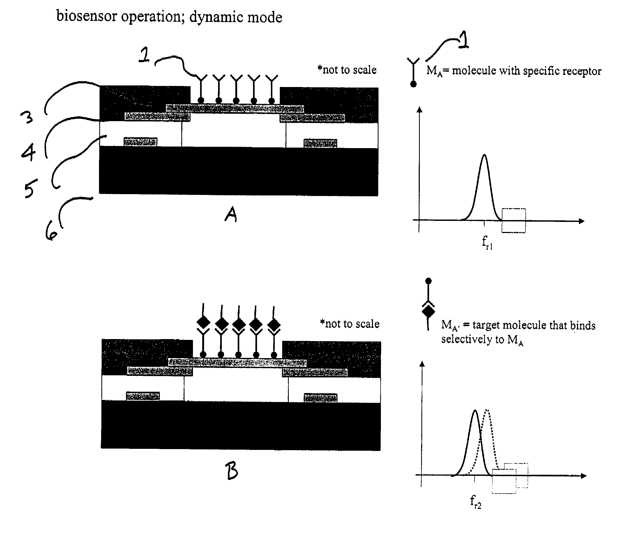
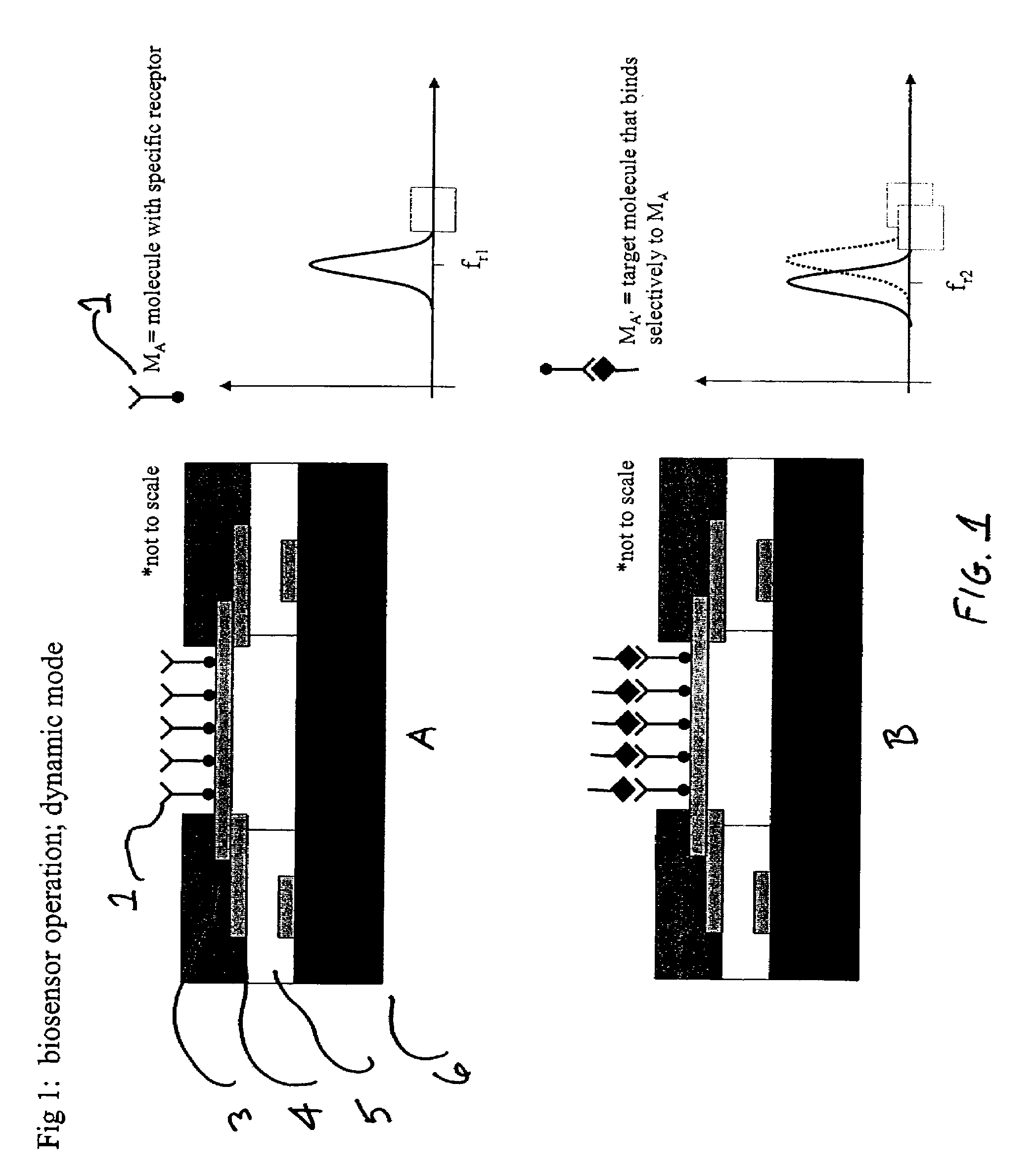
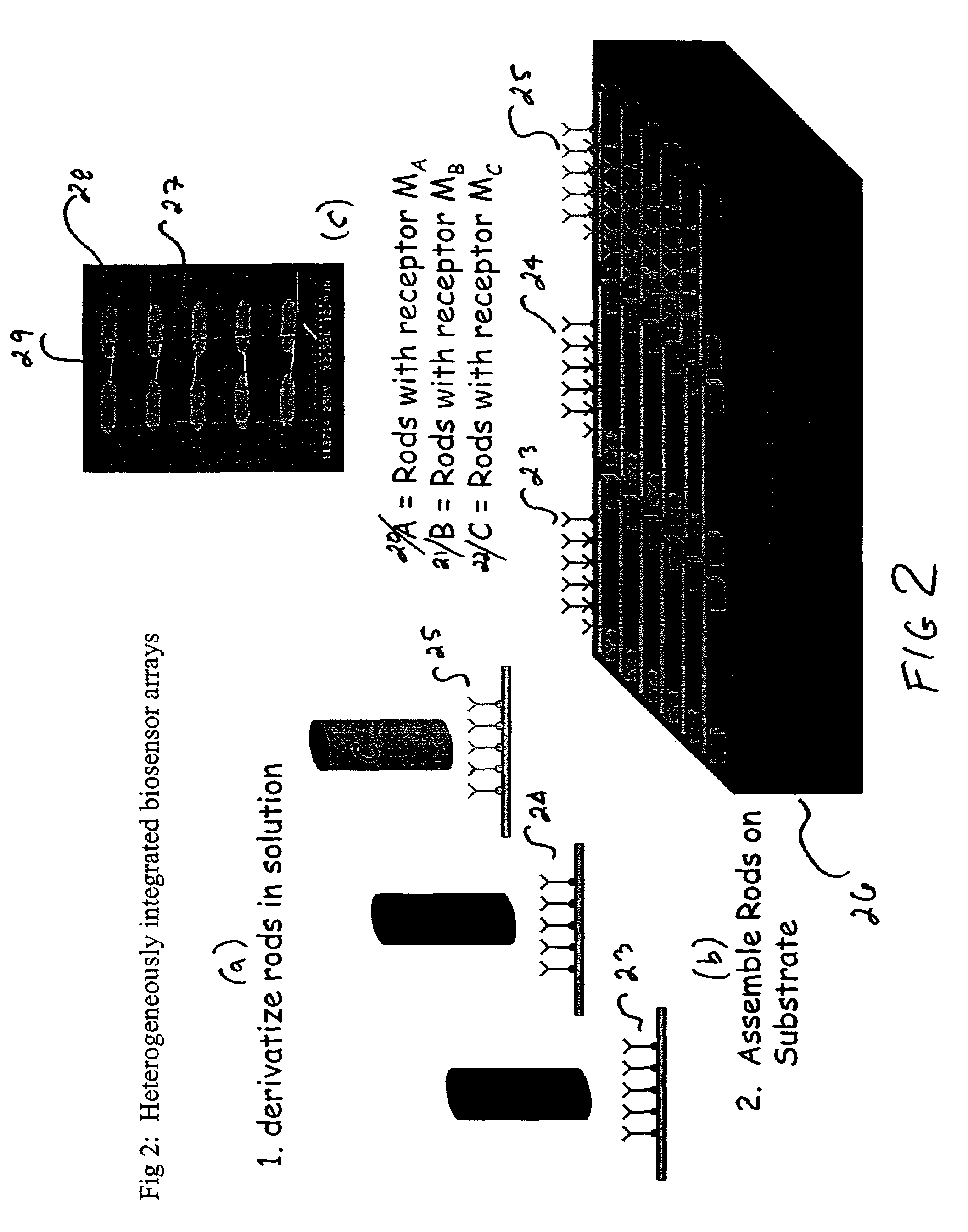
[0063]Several nanorod integration schemes are possible. Here, we will provide a process flow for one scheme that can be used for molecule assembly onto the rods prior to their integration. This process flow is outlined in FIG. 1. There are many other schemes that could be envisioned for those who are skilled in the art of process integration. These involve assembling the rods prior to molecule integration and assembling the molecule using orthogonal assembly onto different metal rods OR through electric-field enhanced assembly of the molecules.

[0064]Step 1-Rod Synthesis: Using the template replication approach described previously, we synthesize rods and suspend them in a solvent that is compatible with molecule assembly.

[0065]Step 2-Receptor Molecule Assembly: In this example, we have three vials of rods with different receptor molecules MA, MB, and MC in each vial. Using template replication techniques, we synthesize and functionalize >1011 rods simultan...


PUM

PropertyMeasurementUnit
diameteraaaaaaaaaa
lengthaaaaaaaaaa
sizeaaaaaaaaaa

Abstract

The invention provides sensor, preferably biosensor devices and method of fabrication. The devices have significant advantages over the prior art methods having compatibility with future trends in clinical diagnostics and chemical detection. The underlying principle involves the integration of nanometer diameter, micron long metal or semiconductor rods onto a substrate to form a suspended nanomechanical cantilevers. The cantilever rods are rigidly attached to the substrate on one or both ends, and resonate at a characteristic frequency depending on the diameter, length, and stiffness of the rod. The metal or semiconductor rods are integrated onto the substrate using electrofluidic or fluidic assembly techniques. A receptor coating is placed on the metal or semiconductor rods prior to or following rod alignment using self-assembly chemistries. Sensing is accomplished when the target agent binds to the receptor substance, causing a change in the mass of the cantilever rod, and a corresponding change in the resonant frequency. This change in resonant frequency can be detected using an electrical readout. The sensing circuitry is integrated with CMOS or TFT technologies to form compact multi-analyte senor arrays on single crystal silicon, glass, or polymeric substrates. Circuits can also be included on the substrate to transmit the array data via wireless methods to a remote workstation for analysis. Devices may be integrated on chips with other analysis devices.

Description

[0001]This application claims priority from U.S. Provisional Application Ser. No. 60 / 377,099 filed Apr. 26, 2002.[0002]This application was supported by ONR / DARPA grant number N00014-98-1-0846. Accordingly the US government may have certain rights in this invention.BACKGROUND OF THE INVENTION[0003]1. Field of the Invention[0004]The present invention relates to the field of heterogeneously integrated sensor arrays, preferably biosensor arrays. In particular, the invention relates to nanomechanical cantilever type biosensors for detecting target-receptor molecule binding, which produce an electrical detection signal upon change in cantilever mass or static deflection. The invention also relates to the manufacture of nanomechanical cantilever biosensor arrays by parallel assembly of many different biomolecule derivatized nanorods onto single silicon or thin-film electronic circuits using “bottom-up” integration strategies.[0005]2. Description of the Prior Art[0006]During the past decad...

Claims


Application Information

Patent Timeline
Patent Type & Authority Patents(United States)
IPC IPC(8): G01N1/31C12Q1/68G01N33/543
CPCG01N33/54373Y10S977/702Y10S977/877
Inventor MAYER, THERESA S.KEATING, CHRISTINE D.
Owner PENN STATE RES FOUND
Learn More