

Industrial evaporation apparatus
a technology of industrial evaporation and evaporation chamber, which is applied in the direction of evaporation, separation processes, refrigeration components, etc., can solve the problems of poor evaporation efficiency, difficult continuous stable operation, and no description of means for avoiding degeneration, etc., and achieve high viscosity, high efficiency, and high viscosity
- Summary
- Abstract
- Description
- Claims
- Application Information
AI Technical Summary
Benefits of technology
Problems solved by technology
Method used
Image

Examples
example 1
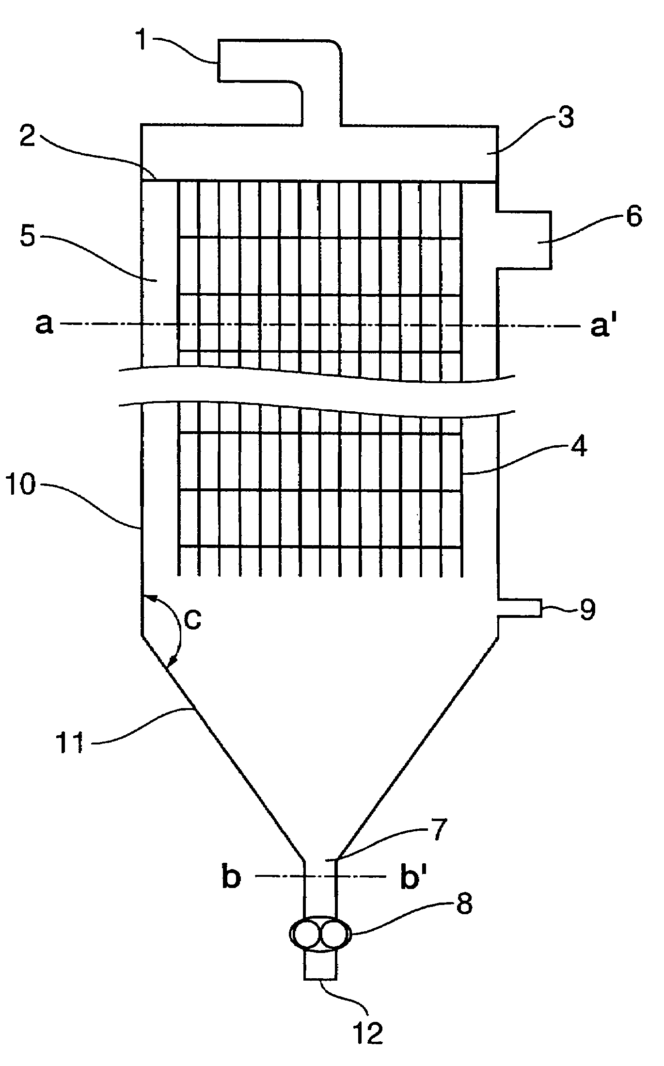
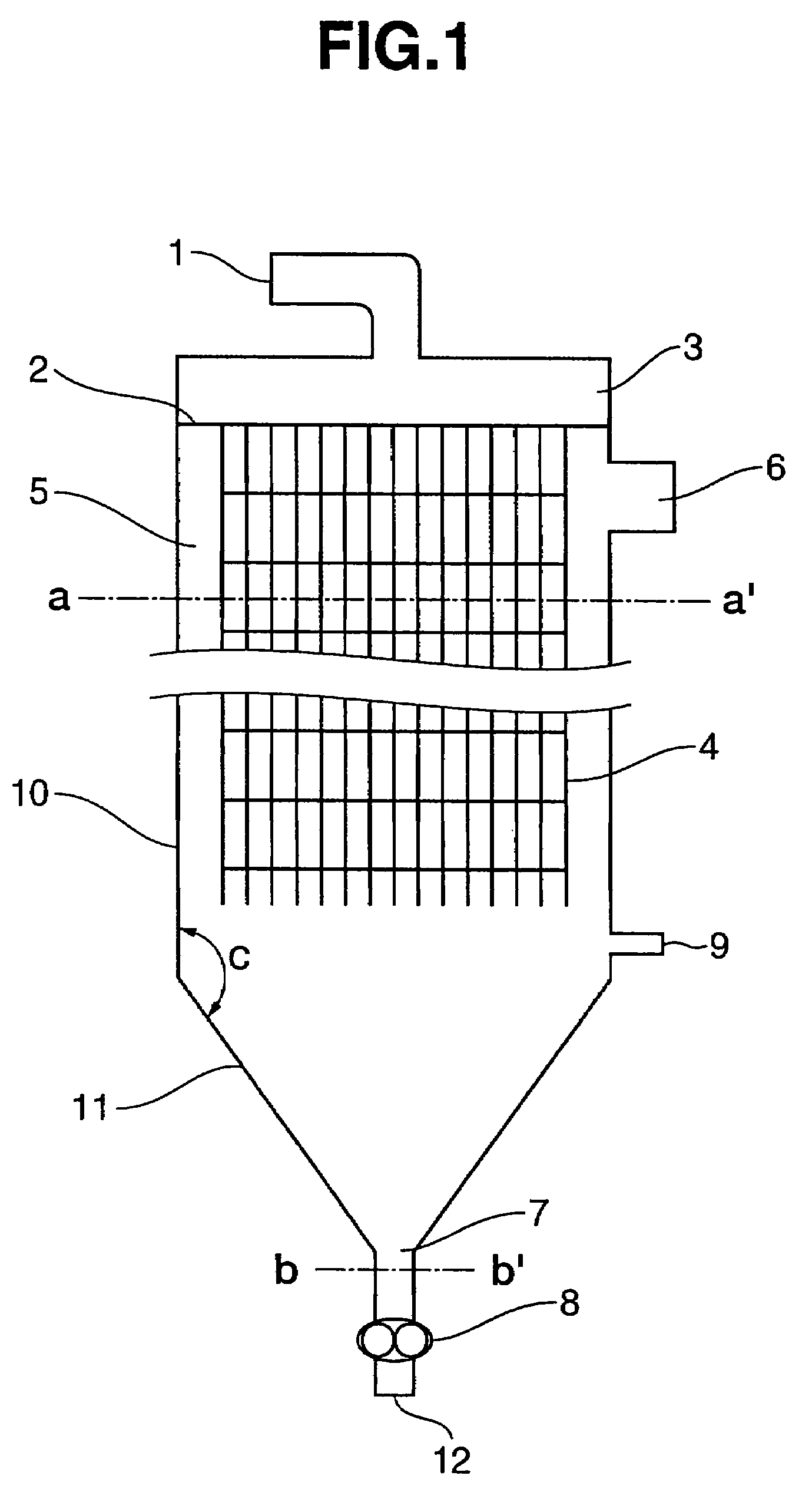
[0081]An industrial evaporation apparatus having a disk-shaped flow path controlling member 20 of thickness approximately 2 cm and guides 4 as shown in FIGS. 2 and 3. The disk-shaped flow path controlling member 20 was fixed suspended from the top thereof such that the spacing from the top internal wall 23 of the liquid feeding zone 3 was approximately 8 cm. Moreover, the spacing between the internal sidewall surface 22 of the liquid feeding zone 3 and the flow path controlling member 20 was approximately 9 cm, and the spacing between the perforated plate 2 and the flow path controlling member 20 was approximately 8 cm. Note that a peripheral portion of the disk-shaped flow path controlling member 20 was designed such that the vertical section thereof was a semicircle of radius approximately 1 cm, and was thus devised such that the liquid would not stagnate around this peripheral portion. Moreover, the section of the joint between the internal sidewall surface 22 of the liquid feedi...
reference example 1
[0082]Using the industrial evaporation apparatus of Example 1 as a polymerization apparatus for a condensation polymer, an aromatic polycarbonate was produced. A molten prepolymer (number average molecular weight Mn=4,000) for the aromatic polycarbonate that had been produced from bisphenol A and diphenyl carbonate (molar ratio of diphenyl carbonate to bisphenol A=1.05) and was held at 260° C. was continuously fed into the liquid feeding zone 3 from the liquid receiving port 1 by a feed pump. The molten prepolymer, which was continuously fed into the evaporation zone 5 (polymerization reaction zone) from the holes in the perforated plate 2 while flowing from the peripheral portion toward the central portion of the perforated plate 2, was subjected to polymerization while flowing down along the guides 4. The polymerization reaction zone was held at 80 Pa via a vacuum vent 6. Produced aromatic polycarbonate entering into the bottom portion 11 of the polymerization apparatus from the b...
example 2
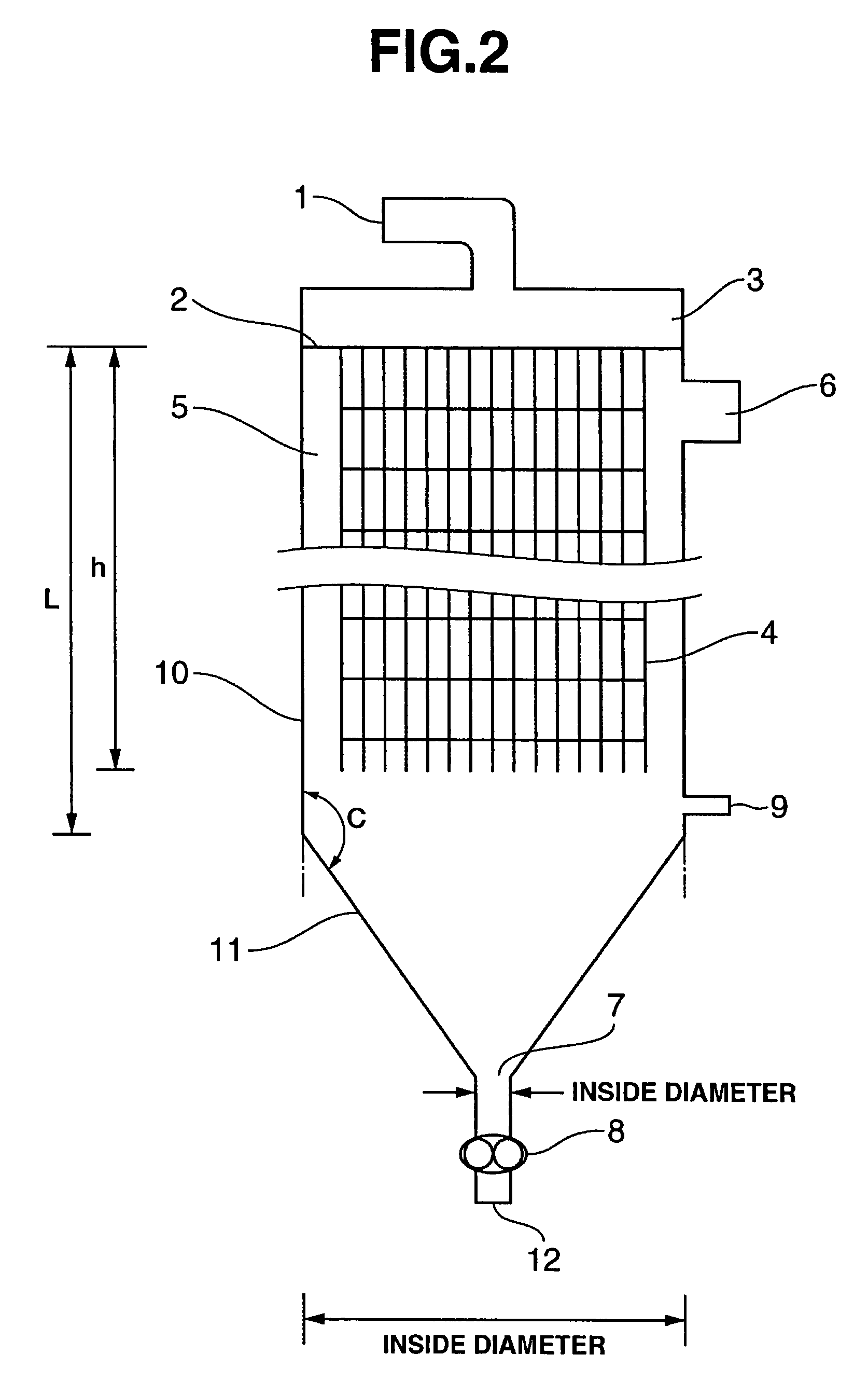
[0085]Polymerization equipment for a condensation polymerization type polymer in which two industrial evaporation apparatuses each having a flow path controlling member 20 and guides 4 as shown in FIGS. 2 and 3 are arranged in series. An aromatic polycarbonate was produced using this polymerization equipment (first polymerization apparatus plus second polymerization apparatus). The material of the evaporation apparatuses was all stainless steel. The discharging pump 8 for each of the evaporation apparatuses was a gear pump. The first polymerization apparatus, which was of a guide-contacting downflow type, had a cylindrical side-wall casing 10 and a conical bottom-wall casing 11, and was such that L=950 cm, h=850 cm, D=400 cm, d=20 cm, C=150°, S=750 m2, A=12.56 m2, A / B=400, D / d=20, L / D=2.375, and r=0.3 cm. Note that the diameter of the cross section of the flow path controlling member 20 was a little small, but this cross section had the same shape as in Example 1, and the spacings b...
PUM
| Property | Measurement | Unit |
|---|---|---|
| angle | aaaaa | aaaaa |
| area | aaaaa | aaaaa |
| area | aaaaa | aaaaa |
Abstract
Description
Claims
Application Information