
Seismic exploration and imaging system for producing survey reports of subsea geological structures

a seismic imaging and subsurface technology, applied in the direction of optical radiation measurement, instruments, spectrometry/spectrophotometry/monochromators, etc., can solve the problems of ineffective 4c acquisition system, ineffective 4c imaging system, and prohibitively expensive cost of geophone positioning and re-positioning on the sea bed

Active Publication Date: 2010-02-09
INNOVA AS
View PDF13 Cites 30 Cited by
  • Summary
  • Abstract
  • Description
  • Claims
  • Application Information

AI Technical Summary

Benefits of technology

[0015]The z-component of the surface particle velocity is similar to the pressure component which will be measured with a mounted hydrophone on the monitoring device. This redundant measurement can be used to calibrate the system and make it more robust against ambient noise and system noise.
[0019]Due to the seismic wavelengths, the particle velocity may be in phase within a 5 m disc on the surface. Therefore groups of spatial distributed cameras can be used to increase signal to noise ratio in one seismic recording channel.
[0021]Due to slower variation in these full field wave field measurements than in the speckle pattern picture, the time sampling rate can be lower, more in the order of the seismic time sampling (ms).
[0030]The relative movement in the OBM vessels / cables can also be partly predicted / eliminated by processing data from several recorders which at the same time, but from different places on the vessel / cable more or less record the same part of the wavefront. This can be achieved with a camera separation less than a wavelength of the seismic wave. If the resolution in the recording is good enough, relative positioning of the recorders can be derived by image analysis and the towing noise can be predicted as a result.

Problems solved by technology

However, the costs involved in positioning and re-positioning geophones on the sea bed in addition to the use of hydrophones has been found to be prohibitively costly.
Unfortunately, 4C-imaging did not become the success that was expected, primarily due to the combination of extreme high acquisition cost and uncertainties in the prediction of payback.
The cost factor is related to capacity problems in available acquisition techniques.
Both due to this static recording component in the acquisition and due to a limited number of available receivers, these 4C acquisition systems become ineffective.
Due to physical problems both related to moving the heavy equipment along the water bottom and geophone coupling, the reliability is adversely affected.
However, as mentioned, S-waves do not travel through sea water, making direct sensing remote from the seabed impossible.
Remote sensing has further inherent problems in that the detection apparatus is subjected to ocean currents which can inhibit effective positioning of the detection apparatus, and introduce noise into measurements, making correlation of the results very difficult.

Method used


Image

  • Seismic exploration and imaging system for producing survey reports of subsea geological structures
  • Seismic exploration and imaging system for producing survey reports of subsea geological structures
  • Seismic exploration and imaging system for producing survey reports of subsea geological structures

Examples


Embodiment Construction

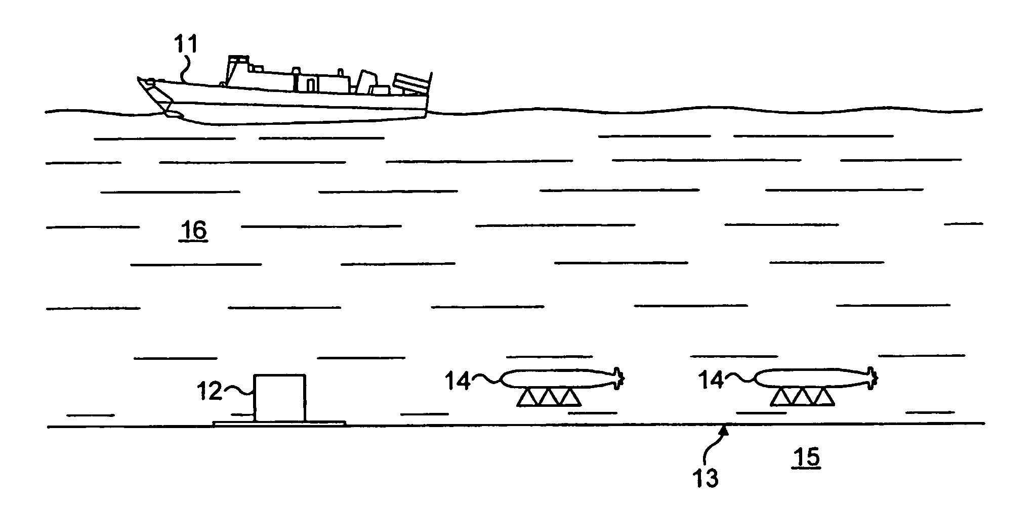
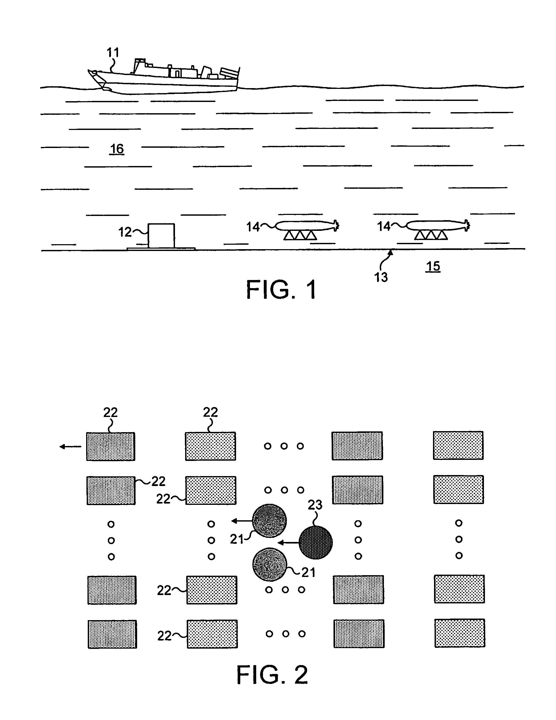
[0036]Referring to FIG. 1, the operation is controlled by a surface vessel 11. A seismic source 12 is located on the seabed 13 and a series of mobile camera units 14 (of which two are shown) monitor the response at the seabed 13 to a seismic wave generated by the source 12. The camera units 14 are positioned about a metre above the seabed 13.

[0037]The camera units 14 each include a light transmitter, a receiver, a hydrophone, an accelerometer and a processing unit. The transmitter transmits light in the form of expanding rays, concentrated rays, modulated light and / or three independent rays. The receiver may comprise a full field array, a coupled array or a single detector.

[0038]The hydrophone is present to measure seismic P-waves above the sea bottom 13. The accelerometer measures camera oscillations in the 0-200 Hz range. The processing unit serves to filter noise (camera oscillations) from the measurements taken, to recognise and detect image objects, to measure image object valu...


PUM


Abstract

The present invention provides a seismic exploration and imaging system for producing seismic survey reports of subsea geological structures. The exploration system provides a method in which both P-waves and S-waves are detected without the need for placing detection apparatus in contact the seabed. A seismic event is applied (12) to the earth's surface (13), and the detected response including P-waves and S-waves in the earth's. The detecting apparatus comprises a means for monitoring and recording the response to the seismic event in the form of movements of particles at the earth's surface, from a position spaced from the earth's surface. Particles at the surface will respond both to P-wave and S-wave stimulation and so their movements will be representative of the two waves. These movements are detected from a distance.

Description

RELATED APPLICATION[0001]This application claims priority to PCT Application No. PCT / GB2003 / 002823 filed Jun. 30, 2003, and Great Britain Application No. 0215214.8 filed Jul. 1, 2002.TECHNICAL FIELD[0002]The present invention relates to seismic exploration techniques and the seismic imaging of subsurface layers. It is particularly but not exclusively concerned with submarine seismic exploration and with producing seismic survey reports of subsea geological structures.BACKGROUND OF THE INVENTION[0003]Conventional seismic methods for exploring subterranean strata beneath the seabed involve generating a seismic wave and measuring the response. The seismic wave may be simple or complex and may be generated at sea level, beneath the surface of the water or at the seabed. The response is detected by a series of spaced receivers which are commonly positioned on cables towed behind an exploration vessel. Generally, the receivers are held stationary for the detection step and are then moved ...

Claims


Application Information

Patent Timeline
IPC IPC(8): G01V1/38G01V1/00
CPCG01V1/3808G01V1/18G06T7/20
Inventor MELDAHL, PAUL
Owner INNOVA AS
Learn More