Turbine shroud thermal distortion control

a technology for turbine shrouds and shrouds, which is applied in the field of outer shrouds, can solve the problems of reducing affecting the performance of the engine, so as to achieve uniform thermal growth, reduce the clearance between the shroud assembly and the turbine blade tip, and reduce the effect of energy consumption

Inactive Publication Date: 2010-02-23
RAYTHEON TECH CORP
View PDF32 Cites 31 Cited by
  • Summary
  • Abstract
  • Description
  • Claims
  • Application Information

AI Technical Summary

Benefits of technology

[0006]The present invention is a means for achieving substantially uniform thermal growth of a shroud suitable for use in a gas turbine engine. By achieving substantially uniform thermal growth, a clearance between the shroud assembly and a turbine blade tip may be minimized, thereby increasing the efficiency of the turbine engine. In a first embodiment, a leading edge of the shroud is impingement cooled while a trailing edge is thermally insulated. In a second embodiment, substantially uniform thermal growth is achieved by varying a coefficient of thermal expansion of the shroud from a leading edge to a trailing edge. In a third embodiment, a shroud achieves substantially uniform thermal growth as a result of an extended portion that extends beyond a width of an adjacent blade tip. In a fourth embodiment, substantially uniform thermal growth is achieved by mechanically applying a clamping force to a leading portion of a shroud in order to help constrain thermal growth of the leading portion. In a fifth embodiment, a shroud includes a leading edge with a greater thickness than a trailing edge thickness. In a sixth embodiment, a shroud includes a plurality of slots along a leading edge, which help limit the amount of thermal expansion of the shroud.

Problems solved by technology

The leakage reduces the amount of energy that is transferred from the gas flow to the turbine blades, which may penalize engine performance.
Many components in a gas turbine engine, such as a turbine blade and shroud, operate in a non-uniform temperature environment.
The non-uniform temperature causes the components to grow unevenly and in some cases, lose their original shape.
In the case of a shroud, such uneven deformation may affect the performance of the gas turbine engine because the tip clearance increases as the shroud expands radially outward (away from the turbine blades).

Method used


Image

  • Turbine shroud thermal distortion control
  • Turbine shroud thermal distortion control
  • Turbine shroud thermal distortion control

Examples


first embodiment

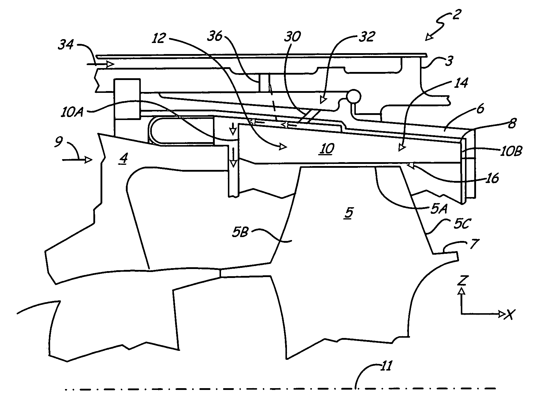
[0030]In the first embodiment, an inventive cooling system includes directing cooling air toward leading portion 12 of shroud 10 through cooling holes 30 in metal support 6, as indicated by arrow 32. More specifically, the cooling air is bled from the compressor section (using a method known in the art) through flow path 34, through cooling holes 36 in casing 3, and through cooling holes 30 in metal support 6. The cooling air then flows across leading portion 12 of shroud 10 and across leading edge 10A of shroud 10. In one embodiment, cooling air from cooling holes 30 in metal support 6 is directed at aft side 12A of leading portion 12 of shroud 10. Cooling leading portion 12 of shroud 10 helps even out the axial temperature variation across shroud 10 because leading portion 12 is typically exposed to higher operating temperatures than trailing portion 14. Although a cross-section of turbine stage 2 is illustrated in FIG. 1, it should be understood that multiple cooling holes 30 are...

second embodiment

[0036]FIG. 4A is a cross-sectional view of achieving substantially uniform thermal growth, where a coefficient of thermal expansion (CTE) of shroud 100 increases from leading edge 100A to trailing edge 100B. Orthogonal x-z axes are provided in FIG. 4A (which correspond to the orthogonal x-y-z axes shown in FIG. 2A) to illustrate the cross-section of shroud 100. Shroud 100 exhibiting a CTE that increases from leading edge 100A to trailing edge 100B may be formed by any suitable method, such as by depositing a plurality of layers having different CTE values, or gradually increasing the percentage of a high CTE material as the material for shroud 100 is deposited. In shroud 100 illustrated in FIG. 4A, plurality layers 102 of ceramic material are deposited, with each succeeding layer of material having a greater CTE value than the previously deposited layer of material. Layer 102A is closest to leading edge 100A of shroud 100, layer 102B is closest to trailing edge 102B, and layer 102C ...

third embodiment

[0040]FIG. 5 is a schematic cross-sectional view of shroud 200, which achieves substantially uniform thermal growth as a result of extending shroud 200 beyond width WBT of adjacent turbine blade tip. Specifically, extended portion 200A extends from main shroud portion 200B. During operation of a gas turbine engine, heat is typically transferred to shroud 200 by combustion gas. As blade 202 rotates, it incidentally circulates the hot gases towards main shroud portion 200B of shroud 200. Extended portion 200A, however, is subject to less heat transfer from blade 202 passing, because extended portion 200A is not directly adjacent to blade 202, and is therefore exposed to a lower heat transfer rate and encounters less thermal growth than main shroud portion 200B. Main shroud portion 200B is aligned with blade 202 and is in the direct path of the hot combustion gases as blade 202 passes under main shroud portion 200B. As a result, main shroud portion 200B undergoes a greater amount of th...


PUM

PropertyMeasurementUnit
temperatureaaaaaaaaaa
slot width Wsaaaaaaaaaa

Abstract

A shroud suitable for use in a gas turbine engine exhibits substantially uniform thermal growth.

Description

STATEMENT OF GOVERNMENT INTEREST[0001]This invention was made with Government support under contract number W31P4Q-05-D-R002, awarded by the U.S. Army Aviation and Missile Command Operation and Service Directorate. The U.S. Government has certain rights in this invention.CROSS-REFERENCE TO RELATED APPLICATION(S)[0002]Reference is made to co-pending U.S. patent application Ser. No. 11 / 502,212, entitled CERAMIC SHROUD ASSEMBLY, filed on the same date as this application.BACKGROUND[0003]The present invention relates to an outer shroud for use in a gas turbine engine. More particularly, the present invention relates to a means for achieving substantially uniform thermal growth of an outer shroud.[0004]In a gas turbine engine, a static shroud is disposed radially outwardly from a turbine rotor, which includes a plurality of blades radially extending from a disc. The shroud ring at least partially defines a flow path for combustion gases as the gases pass from a combustor through turbine ...

Claims


Application Information

Patent Timeline
Patent Type & Authority Patents(United States)
IPC IPC(8): F01D11/08
CPCF01D11/24F01D25/12F01D11/18F01D25/14F05D2300/21
Inventor SHI, JUNGREEN, KEVIN E.BUTLER, SHAOLUO L.SRINIVASAN, GAJAWALLI V.LEVASSEUR, GLENN N.
Owner RAYTHEON TECH CORP
Why Eureka
Try Eureka