Electrodeposition display panel manufacturing method, electrodeposition display panel, and electrodeposition display device

a display panel and display panel technology, applied in the manufacture of electric discharge tubes/lamps, discharge tubes luminescnet screens, instruments, etc., can solve the problems of difficult hermetically sealing the openings and the display material itself is not easily filled, and achieve the effect of high-reliability display panels in a short time and efficient

Inactive Publication Date: 2010-02-23
SONY CORP
View PDF20 Cites 38 Cited by
  • Summary
  • Abstract
  • Description
  • Claims
  • Application Information

AI Technical Summary

Benefits of technology

[0013]In view of the foregoing problems, it is an object of the present invention to provide an electrodeposition display panel manufacturing method capable of manufacturing a highly reliable display panel in a short time and efficiently, an electrodeposition display panel, and an electrodeposition display device.
[0015]In the electrodeposition display panel manufacturing method of the present invention, not only the display material is injected from the first opening, but also the display material is concurrently discharged from the second opening. Thereby, the display material is immediately filled in the cell. In general, the display material is the electrolytic solution, in which metal ions, a pigment, a dye, a cross-linked high molecular weight material for gelation and the like are dissolved. The display material has a high viscosity, and has characteristics that the display material itself is not easily filled. However, the space of the electrodeposition display panel is considerably wide, being generally about 30 μm to 150 μm, compared to the layer thickness of liquid crystal in the liquid crystal panel (about 5 μm or less). Therefore, while in the liquid crystal panel, liquid crystal is filled by mainly utilizing capillary phenomenon, filling the display material by pressurization is suitable in the electrodeposition display panel. This method is suitably applicable to, for example, the display material having a viscosity of 30,000 mPa·s or less measured by a rotating viscometer where the rotor frequency is 0.5 rpm. Then, when discharging the display material is performed under depressurization as appropriate, the filling time can be shortened. As above, when the display material is injected at the pressure equal to or more than the normal pressures, composition alteration due to volatilization is not caused. In addition, even if the display material with a high viscosity is injected, or even if the injection resistance becomes larger since a separation preventive layer is formed on the substrate, injection can be performed in a relatively short time. Further, by discharging the display material from the second opening immediately after starting filling, air bubbles remaining in the cell, powder materials whose constituent is separated in the cell during filling, and unnecessary matters such as an electrolytic solution are pushed out together, and therefore the display material with a uniform composition can be filled all over inside the cell.
[0016]Further, the first and the second openings are preferably formed in the substrate. As described above, the side edge of the electrodeposition display panel is made of a sealing material such as an adhesive film. Though the openings are provided therein in the traditional vacuum injection method as well, hermetically sealing the openings is more difficult than in thin liquid crystal panels. Further, the substrate to be opened is more preferably a resin substrate such as glass epoxy, which is more easily processed.
[0017]Further, in the foregoing step, it is preferable that after the nozzle is temporarily attached to at least one of the first and the second openings, the display material is injected and discharged. By using the nozzle, adjustment of pressurization and depressurization to the inside of the cell can be conveniently and immediately performed. Further, the display material to be injected and discharged is prevented from being contacted to the cell, and after that, the opening can be effectively and surely sealed. Further, when the nozzle is not used, by covering the outer circumference of the opening with a mask, the display material is prevented from being contacted to the cell, and after that, the opening can be effectively and surely sealed.

Problems solved by technology

The display material has a high viscosity, and has characteristics that the display material itself is not easily filled.
Though the openings are provided therein in the traditional vacuum injection method as well, hermetically sealing the openings is more difficult than in thin liquid crystal panels.

Method used


Image

  • Electrodeposition display panel manufacturing method, electrodeposition display panel, and electrodeposition display device
  • Electrodeposition display panel manufacturing method, electrodeposition display panel, and electrodeposition display device
  • Electrodeposition display panel manufacturing method, electrodeposition display panel, and electrodeposition display device

Examples


example 1

[0111]Respective mixing amounts of the following constituents were dissolved in dimethyl sulfoxide to prepare an electrolytic solution.

[0112]Silver iodide: 500 mmol / l

[0113]Sodium iodide: 750 mmol / l

[0114]Triethanolamine: 67 mmol / l

[0115]Coumarin: 5 g / l

[0116]2-Mercaptobenziimidazole: 5 g / l

[0117]Into the foregoing electrolytic solution, a fifth weight resin liquid, TA-140 (manufactured by Dai-ichi Kogyo Seiyaku Co., Ltd.) was mixed to prepare an electrolytic solution. As a white pigment, titanium oxide, JR-805 (manufactured by Titan Kogyo K.K.) being weighing equal to the electrolytic solution was added to the electrolytic solution, and dispersed by a homogenizer. The resultant was accommodated in a desiccator, depressurized by an oil diffusion pump until when bubbles were not produced from the electrolytic solution in which the pigment was dispersed. To the resultant, an organic oxide, Perocta O (manufactured by NOF Corporation) was added at a ratio of 2 wt % of the resin solution, whi...

example 2

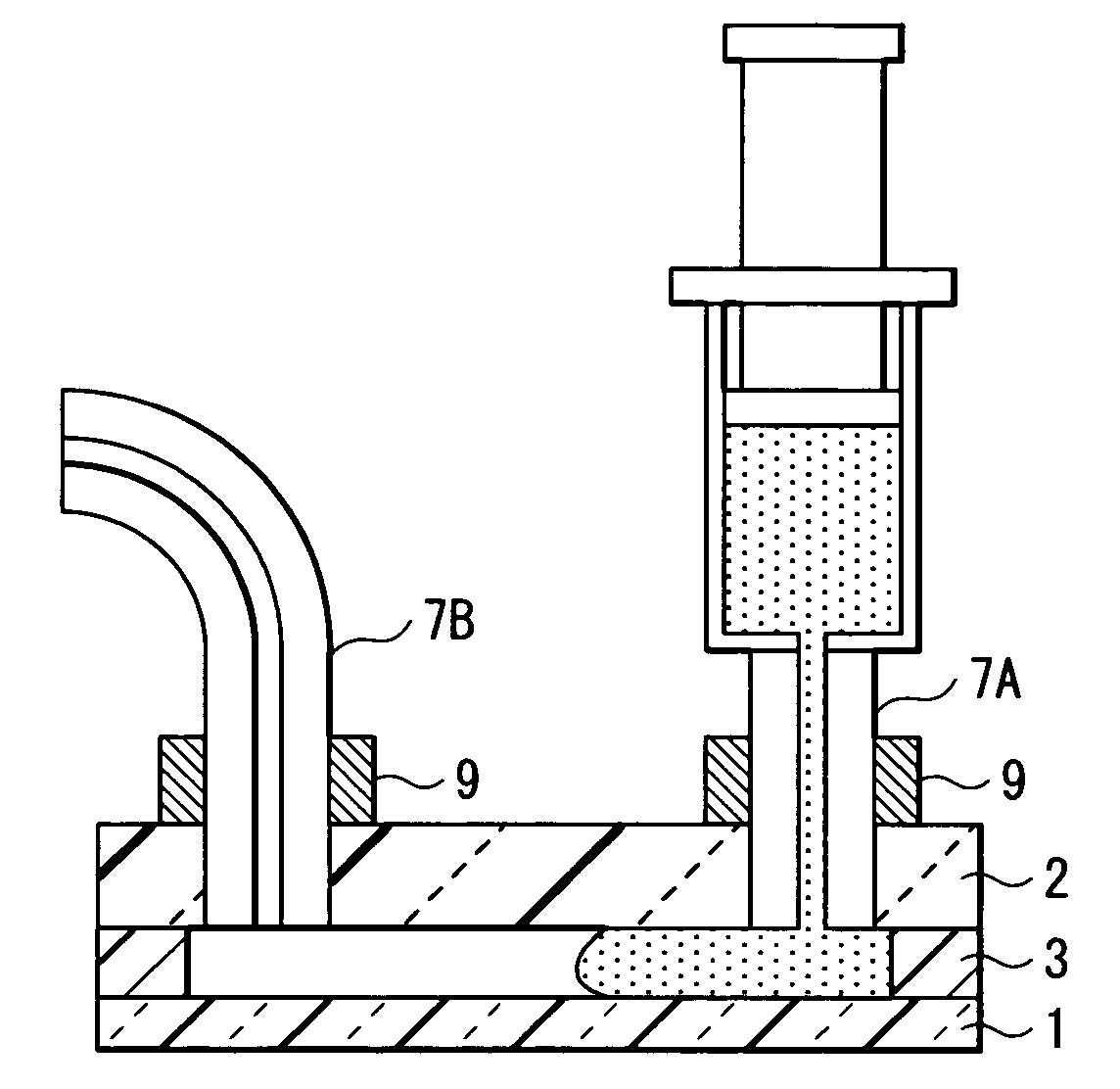
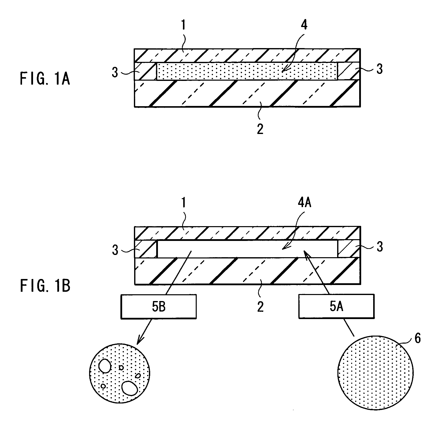
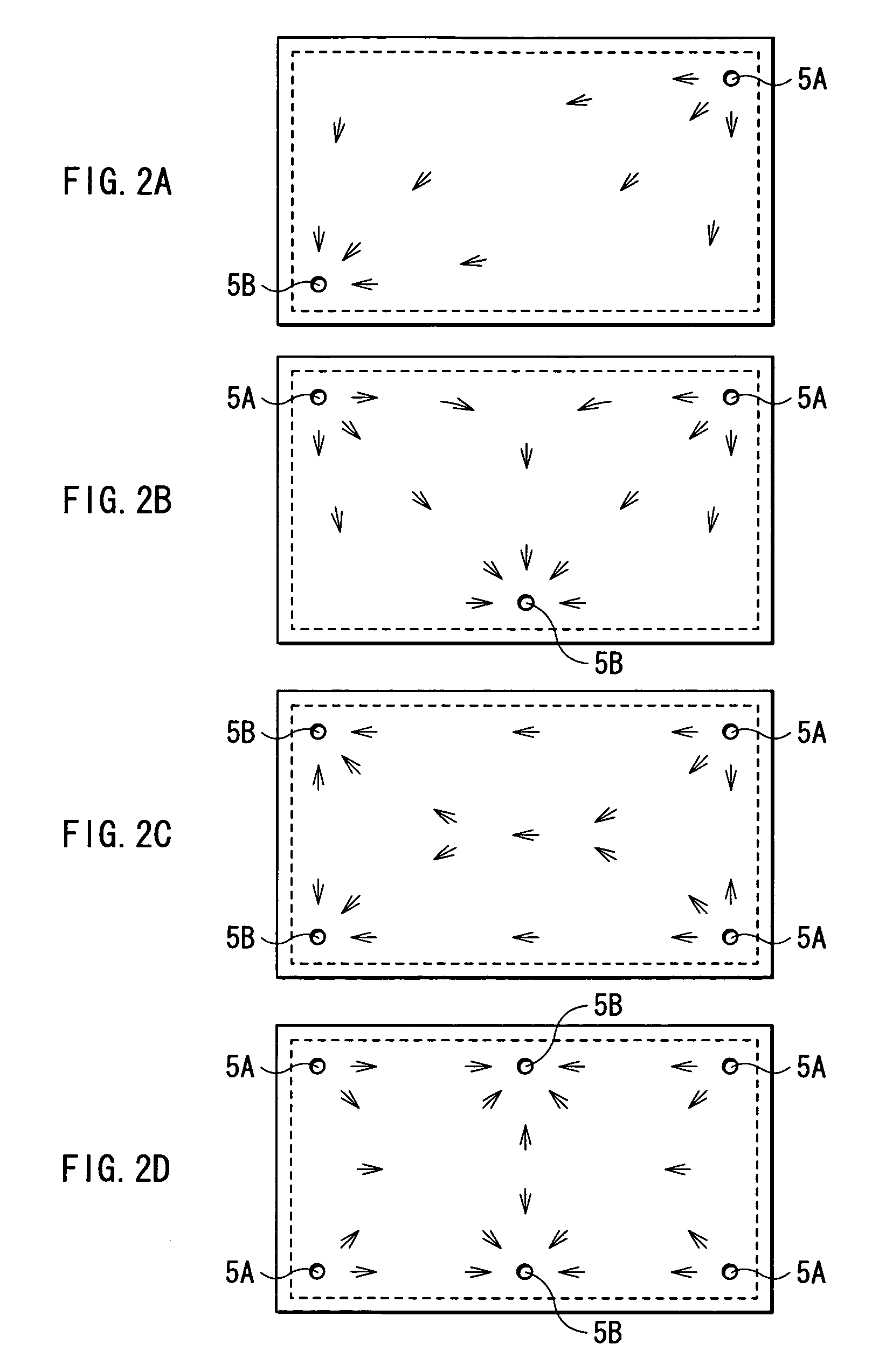
[0121]A PET film 51 was affixed to the whole rear face of the glass epoxy substrate (rear substrate 2), which is the same as used in Example 1. As an adhesive, a synthetic rubber spray glue (manufactured by Sumitomo 3M Ltd.) was used. As in Example 1, in the opposing corners of the substrate 2, the circular opening 5A being 4.0 mm in diameter and the circular opening 5B being 2.0 mm in diameter were drilled. The film type hot melt adhesive 3 and the transparent electrode substrate 1, both of which are the same as used in Example 1 were used to assemble a cell.

[0122]The display material 6 was sucked in the 10 ml injector 8 made of polypropylene, to which a threaded nozzle was connected, and the nozzle was screwed in the opening 5A. The inside of the opening 5A and the opening 5B was sandwiched by using acrylic plates being 1 cm thick from the both sides of the cell. The cell was fixed by a clamp with the glass epoxy substrate 2 to which the injector 8 was connected held downward and ...

example 3

[0124]In the opposing corners of the glass epoxy substrate (rear substrate 2), the same as used in Example 1, the circular opening 5A being 4.0 mm in diameter and the circular opening 5B being 2.0 mm in diameter were screw-cut and drilled. The film type hot melt adhesive 3 and the transparent electrode substrate 1, the same as used in Example 1 were used to assemble the cell.

[0125]The display material 6 was sucked in the 10 ml injector 8 made of polypropylene to which a threaded nozzle was connected, and the nozzle was screwed in the opening 5A. Of the both faces of the cell, the inside of the opening 5A and the opening 5B was sandwiched by using acrylic plates being 1 cm thick. The cell was fixed by a clamp with the glass epoxy substrate 2 to which the injector 8 was connected held downward and the transparent electrode substrate 1 held upward. The opening 5B was connected to a diaphragm pump through a polyethylene tube whose end was screw-cut in the same gauge as of the opening 5B...


PUM

PropertyMeasurementUnit
viscosityaaaaaaaaaa
heightaaaaaaaaaa
reflectanceaaaaaaaaaa

Abstract

An electrodeposition display panel manufacturing method capable of manufacturing a highly reliable display panel in a short time and effectively, an electrodeposition display panel, and an electrodeposition display device are provided. Openings (5A), (5B) are provided in a rear substrate (2) of the cell. A nozzle (7A) to which an injector (8) is connected on the other side is inserted into the opening (5A), and a nozzle (7B) is inserted into the opening (5B). On the other end side of the nozzle (7B), a container for recovering a spilled display material (6) and a decompressor are arranged. While the display material (6) is pressure-injected from the opening (5A), evacuation and discharging air bubbles and the like are performed from the opening (5B). Thereby, the display material (6) is filled in the cell.

Description

[0001]This application claims priority to Japanese Patent Application Number JP2003-60178, filed Mar. 6, 2003 which is incorporated herein by reference.TECHNICAL FIELD[0002]The present invention relates to a method of manufacturing an electrodeposition display panel for performing display by utilizing electrochemical deposition and dissolution of a metal, in which a display material containing metal ions is sandwiched between a pair of electrode substrates, an electrodeposition display panel manufactured by using the method, and an electrodeposition display device.BACKGROUND ART[0003]In recent years, as networks have become common, documents, which were traditionally distributed in the shape of printed matters have been distributed as so-called electronic documents. Further, books, magazines and the like have been often provided as so-called electronic publishing. However, it is suggested that in terms of reading such information, traditional light emitting displays cause acute tire...

Claims


Application Information

Patent Timeline
Patent Type & Authority Patents(United States)
IPC IPC(8): H01J9/24H01J1/62H01J63/04H01J9/26G02F1/1506G02F1/1341
CPCG02F1/1506G02F1/1341
Inventor SAITO, NORIYUKIITO, YOSHINORI
Owner SONY CORP
Why Eureka
Try Eureka