Renew compression screw

a technology of compression screw and screw body, applied in the field of orthopedics and trauma, to achieve the effect of preserving and augmenting the functions of primary bone implant and enhancing the stability and durability of the implan

Inactive Publication Date: 2010-02-23
DROR PALEY
View PDF10 Cites 29 Cited by
  • Summary
  • Abstract
  • Description
  • Claims
  • Application Information

AI Technical Summary

Benefits of technology

[0067]The invention is aimed at preserving and augmenting the functions of the primary bone implant of the external fixator in which, Axial and Surface preloads are added to the older method of Radial preloading of the implant in bone. This has an added effect on the stability and durability of the implant. The former two preloads are also renewable, because the screw can again be tightened after the first insertion. The triple preload widely distributes stresses away from the interface of rod / drill hole, where loosening of a conventional implant occurs.
[0068]Another embodiment is a lag screw, which can be driven at a mechanically sound right angle to the fracture plane, with renewable compression. Renewed and prolonged inter-fragmentary compression by external fixator is a new advantage to the biology of bone healing.
[0069]This implant can also be used to supplement minimally invasive plate osteosynthesis with double advantage. The torque can be renewed to keep plate firmly on bone and the same implant can form an outside construct to augment the stability of an implanted plate.
[0070]All positive features of the prior implants are retained; permitting wound access, minimal incisions, safe corridor insertion, soft tissue preservation, and no lengthwise invasion of medullary canal of bone. No novel disadvantages are introduced.

Problems solved by technology

The following problems of this method seldom make it the preferred treatment.
1. It is difficult to maintain the traction force continuously even with very frequent attention.
2. Patient cooperation is difficult to achieve.
Distraction and movement of fragments may cause delay or failure of union.
4. Circulatory problems can occur in the distal limb.
5. Wounds in the traction surface will not allow such treatment.
2. Encircling of the part causes sweating and discomfort in hot climates.
5. Swelling of part within the cast can cause tightness and loss of circulation or nerve function.
5. Loosening of cast occurs due to loss of swelling of the part, or due to reduction of the thickness of the padding by moisture, resulting in loss of reduction.6. There is no access to any wounds inside, which may need regular attention, except by cutting out windows or leaving the cast incomplete, which may jeopardize the immobilization, and fracture position.
7. Uninvolved parts also are immobilized, a setback to recovery.
Meticulous technique may minimise this, yet the exposure is larger.b. Compression between fragments once applied at operation wears off within hours, depending on the quality of bone.
There is no possibility of renewing this compression once the wound is closed over the device.
It is not acceptable to re-anaesthetise and re-expose the device repeatedly to re-tighten the screws.c. Minimally invasive methods are performed through smaller incisions but in order to place the plate directly on bone, the periosteum and muscle have to be stripped blindly.
The plate is always unavoidably placed over some soft tissues, which melt away under the pressure and loosen the plate.
Loss of torque of screws is unfavourable to biology of bone healing.d.
The disadvantages are as under.1. It is generally not applicable to children, due to growth plates at the ends of bones.2. It invades and occupies the bone from end to end, with the possibility of spreading infection.3. It is not stable to rotational forces, and interlocking methods are not available for all situations.4. In open nailing, the fracture haematoma is dispersed.D.
The following limitations remain:1. The basic implant e.g. the Schanz screw has a tendency to loosen in bone, leading to instability and a proneness to infection.
Unless such a device is always driven at 90-degrees to the bone surface, the head will stand up on edge, with too much stress concentration at a point, leading to crumbling of bone and loosening.
This would make the engagement surface of head stand up at an angle to the surface leading to mechanical failure and loosening.
This may be the reason, why the device did not gain wide acceptance amongst those skilled in the art, and for the paucity of any reports on its use in English literature.
If compression were applied at 90-degrees to outer bone surface, but not at 90-degrees to fracture plane, it will not only be inefficient but may actually make the fracture surfaces to slide upon each-other rather than be compressed.
For such use as a “traditional” device, it must be considered that an intercalated head adds to the cost of the implant and needs a little larger entry incision.
This could have ruled out its acceptance even as a conventional implant.
Taylor et al thus did not provide for the need of inserting a lag screw device at different angles to the outer surface of bone, which is the crux of the art of lag screw fixation.
Even with such a supplementation, the lag screws can fail, because by the blind stab-hole technique of insertion, there is always some interposition of soft tissue between the screw head and the bone surface.
The only residual control is the external fixator, which may not be adequate for the situation.

Method used


Image

  • Renew compression screw
  • Renew compression screw
  • Renew compression screw

Examples


Embodiment Construction

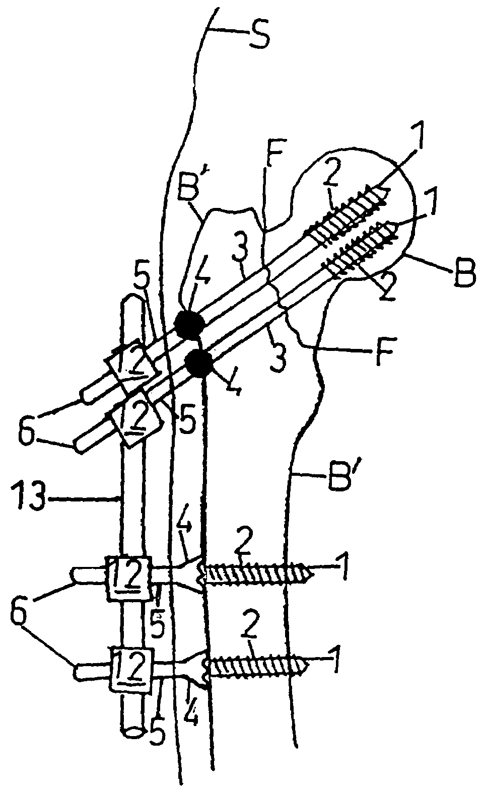
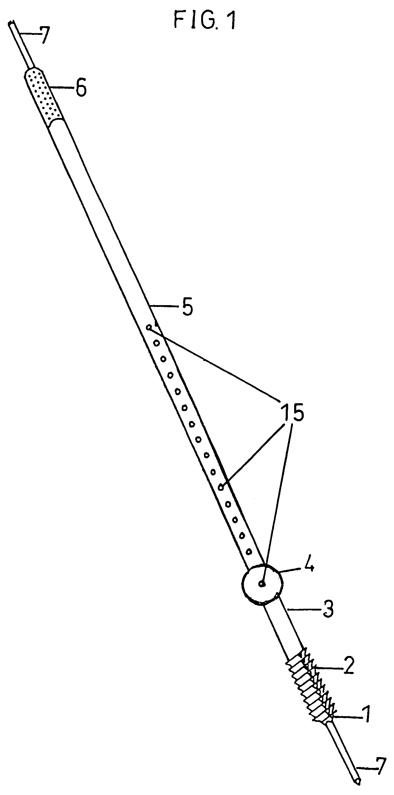
[0082]FIG. 1 is one embodiment of the lag screw implant. In the lag mode it is mainly in tension along its axis and other force vectors are neutralized by the basic construct. It comprises:

[0083]1 being the tip at the first end, with guide wire 7 in the central canal. The tip shown is self tapping, but optionally a non-self tapping tip may be used.

[0084]2 is the short threaded section at the first end, the thread not extending to the head 4.

[0085]3 being the smooth screw shaft section meant for gliding through the drill hole in the fragment nearer to head, allowing lag screw compression.

[0086]4 is the spherical head for engaging a countersunk surface of the fragment nearer to head. The head may be integral with the rod or may be mobile for fixation at a desired level to rod 5.

[0087]Such refixation is provided by means of a transverse screw through the head and drive shaft possessing holes 15, at intervals for screw passage.

[0088]5 is the unthreaded drive shaft, which serves for driv...


PUM


Abstract

An external fixator implant screw with an intercalated head, of which one embodiment for lag screw mode has a spherical head, and a partial thread. The spherical head in countersunk bone exerts concentric wide contact on insertion at various angles to surface. Optional canalization of central rod allows guide wire technique and optional mobility of head allows variable shaft length between head and thread. Another embodiment for use in basic implant mode, in a single bone fragment, at right angles to bone surface, has a conical head with limited basal contact on bone, the head being integrated to a solid rod and is fully threaded from head to leading tip. In both embodiments, the load transmission is renewable from outside in case of loosening, without reopening any wound. The implant is made of biocompatible material.

Description

[0001]Continuation-in-Part Application of U.S. Utility patent application Ser. No. 09 / 643,294, Filed Aug. 22, 2000 now abandoned.CROSS-REFERENCE TO RELATED APPLICATIONS[0002]“Not applicable”STATEMENT REGARDING FEDERALLY SPONSORED RESEARCH OR DEVELOPMENT[0003]“Not applicable”REFERENCE TO A MICROFICHE APPENDIX[0004]“Not applicable”BACKGROUND OF THE INVENTION[0005]This relates to the field of Orthopedics and Trauma, human or veterinary. It can be used for other biological fixations / immobilizations such as botanical or other forms of life and for tissues other than bone. It can be used in any engineering or mechanical endeavour in which it serves to hold and / or compress together fragments or masses of material together, while taking part in an outside construct at a distance from the fragments.[0006]Bone is living tissue. Bone fragments and surfaces can unite by biological activity over a length of time, given proper conditions to favor it. During this biological process of healing, the...

Claims


Application Information

Patent Timeline
Patent Type & Authority Patents(United States)
IPC IPC(8): A61B17/86
CPCA61B17/60A61B17/8625A61B17/8605
Inventor PATHAK, KARTIKEYA P.
Owner DROR PALEY
Why Eureka
Try Eureka