Thermal microphotonic sensor and sensor array

Active Publication Date: 2010-02-23
NAT TECH & ENG SOLUTIONS OF SANDIA LLC +1
View PDF6 Cites 40 Cited by
  • Summary
  • Abstract
  • Description
  • Claims
  • Application Information

AI Technical Summary

Benefits of technology

[0014]In certain embodiments of the present invention, a vertical resonant cavity can also be formed about the infrared absorber to enhance absorption of the infrared radiation. The vertical resonant cavity can be formed with a first mirror located on a top surface of the infrared-absorbing plate, and a second mirror located on the substrate beneath the optical resonator. The first mi

Problems solved by technology

The cooling of MCT detectors consumes considerable electrical power and typically requires a cryostat.
For satellite and UAV applications, the power consumption and weight of cryogenically-cooled quantum detectors can be limiting factors which prevent a scaling of quantum detector

Method used


Image

  • Thermal microphotonic sensor and sensor array
  • Thermal microphotonic sensor and sensor array
  • Thermal microphotonic sensor and sensor array

Examples


Embodiment Construction

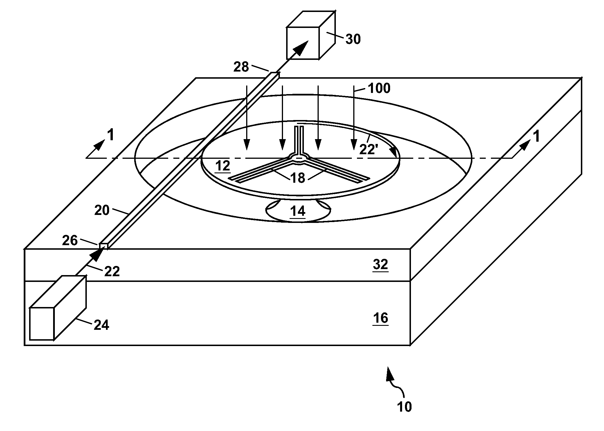
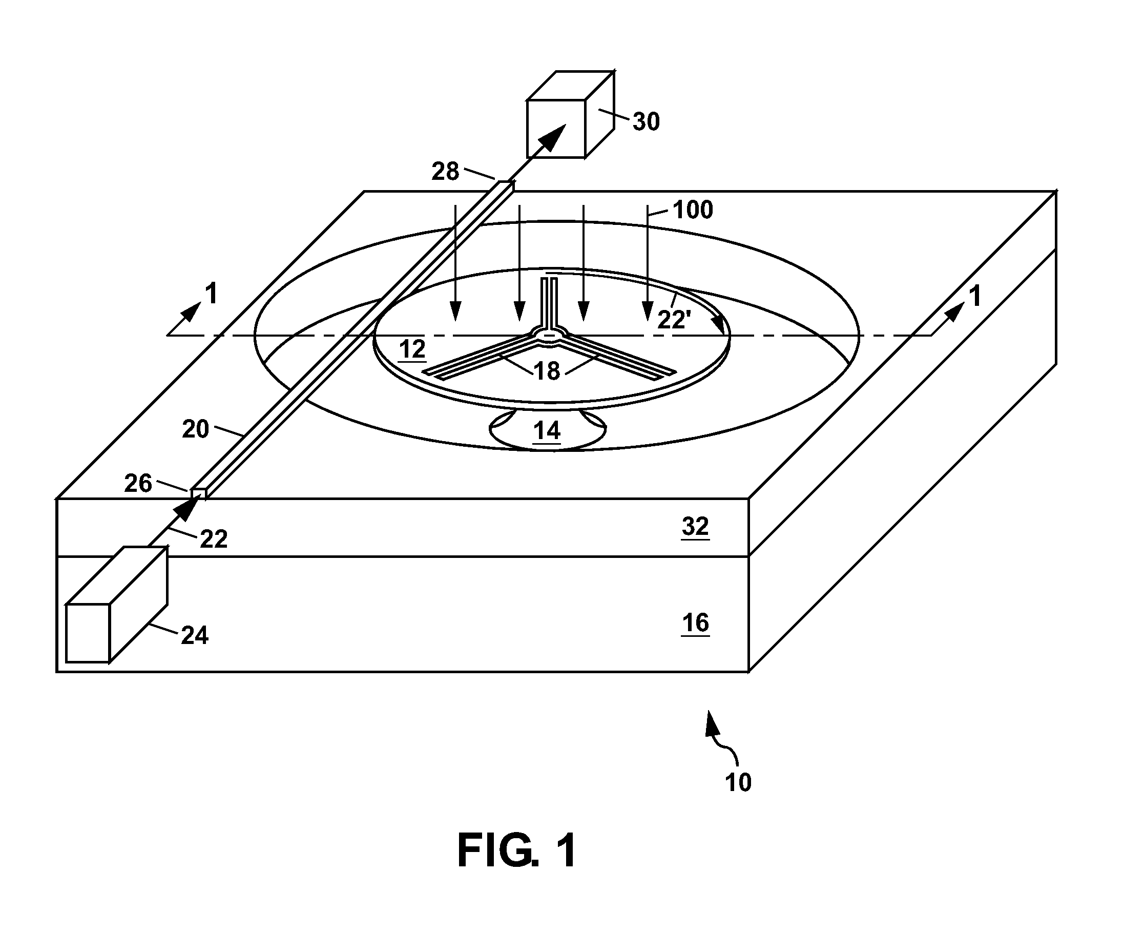
[0040]Referring to FIG. 1, there is shown a schematic perspective view of a first example of a thermal microphotonic sensor 10 of the present invention. The apparatus 10 comprises an optical resonator 12 (also referred to as an optical cavity, a microcavity, or a microring resonator). The optical resonator 12 is suspended on a support post 14 above a substrate 16 by a plurality of tethers 18 which are connected between the optical resonator 12 and the support post 14. An optical waveguide 20 is located near a periphery of the optical resonator 12 to allow an evanescent coupling of light 22 between the optical waveguide 20 and the optical resonator 12.

[0041]The light 22 can be provided by a laser 24 which can be, for example, a single-frequency semiconductor laser such as a distributed Bragg reflector (DBR) laser operating at a wavelength of about 1.5 microns (μm). The light 22 from the laser 24 can be coupled into the optical waveguide 20 at an input end 26 thereof and is transmitte...


PUM


Abstract

A thermal microphotonic sensor is disclosed for detecting infrared radiation using heat generated by the infrared radiation to shift the resonant frequency of an optical resonator (e.g. a ring resonator) to which the heat is coupled. The shift in the resonant frequency can be determined from light in an optical waveguide which is evanescently coupled to the optical resonator. An infrared absorber can be provided on the optical waveguide either as a coating or as a plate to aid in absorption of the infrared radiation. In some cases, a vertical resonant cavity can be formed about the infrared absorber to further increase the absorption of the infrared radiation. The sensor can be formed as a single device, or as an array for imaging the infrared radiation.

Description

GOVERNMENT RIGHTS[0001]This invention was made with Government support under Contract No. DE-AC04-94AL85000 awarded by the U.S. Department of Energy. The Government has certain rights in the invention.FIELD OF THE INVENTION[0002]The present invention relates in general to sensing of infrared radiation, and in particular to a thermal microphotonic sensor which senses infrared radiation by using heat produced by the infrared radiation to change a coupling of light between an optical waveguide and an optical resonator. The thermal microphotonic sensor can be formed as an individual sensor, or as a sensor array which is useful for infrared imaging applications.BACKGROUND OF THE INVENTION[0003]Infrared imaging is useful for detecting electromagnetic radiation at wavelengths beyond that which is visible to the human eye. Infrared imaging has applications for detecting people and / or machines by their emitted heat which is a form of infrared radiation. Such infrared imaging can be performed...

Claims


Application Information

Patent Timeline
IPC IPC(8): G01J5/00
CPCG01J5/08G01J5/0821G01J5/44
Inventor WATTS, MICHAEL R.SHAW, MICHAEL J.NIELSON, GREGORY N.LENTINE, ANTHONY L.
Owner NAT TECH & ENG SOLUTIONS OF SANDIA LLC
Why Eureka
Try Eureka