

Pickup lens
a pick-up lens and lens body technology, applied in the field of pick-up lenses, can solve the problems of inability to use the lens as a compact lens, inability to make the total length of the pickup lens short, and long back focus, so as to achieve the effect of shortening the total length of the pickup lens, not too great spherical aberration, and shortening the optical length l
- Summary
- Abstract
- Description
- Claims
- Application Information
AI Technical Summary
Benefits of technology
Problems solved by technology
Method used
Image

Examples
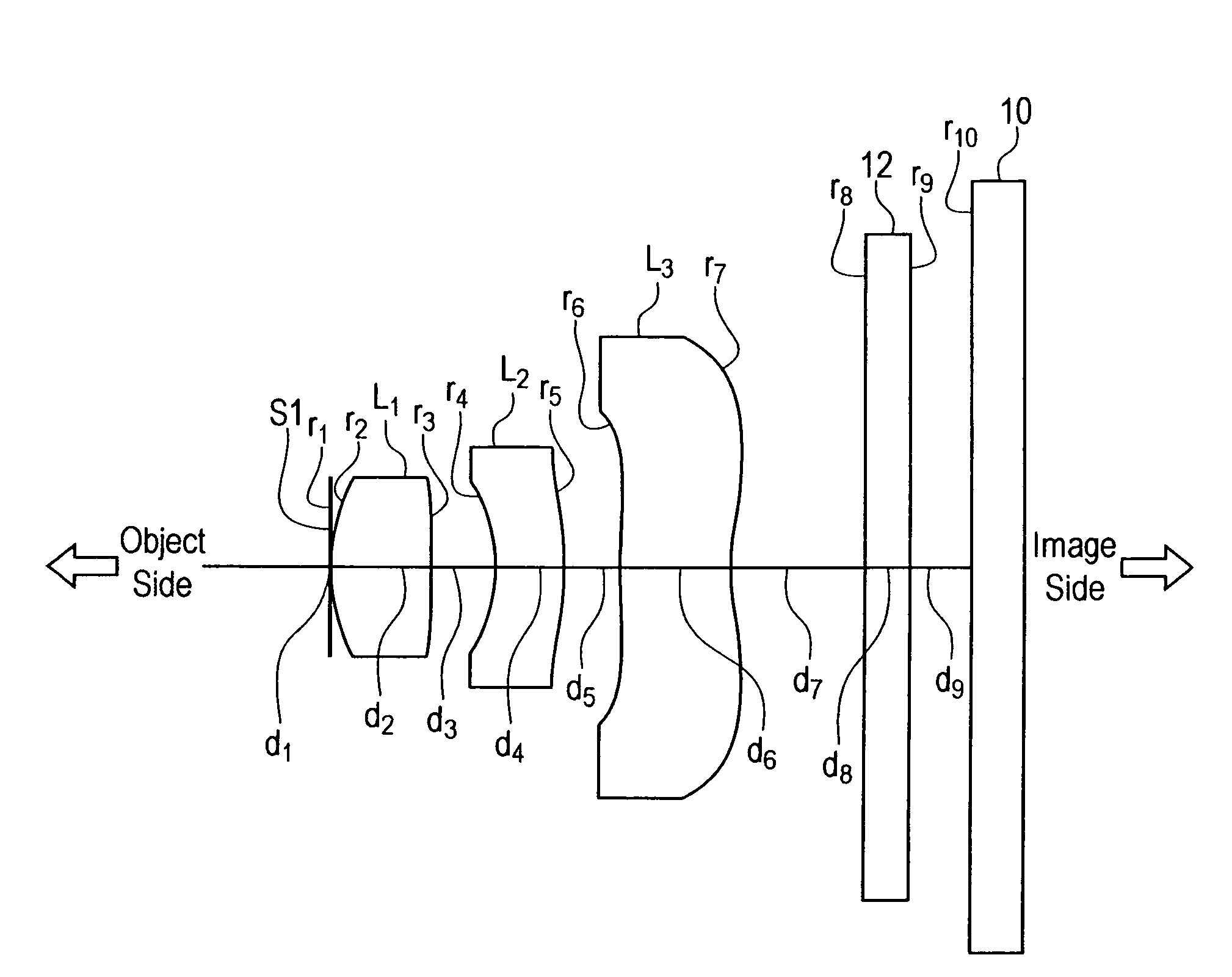
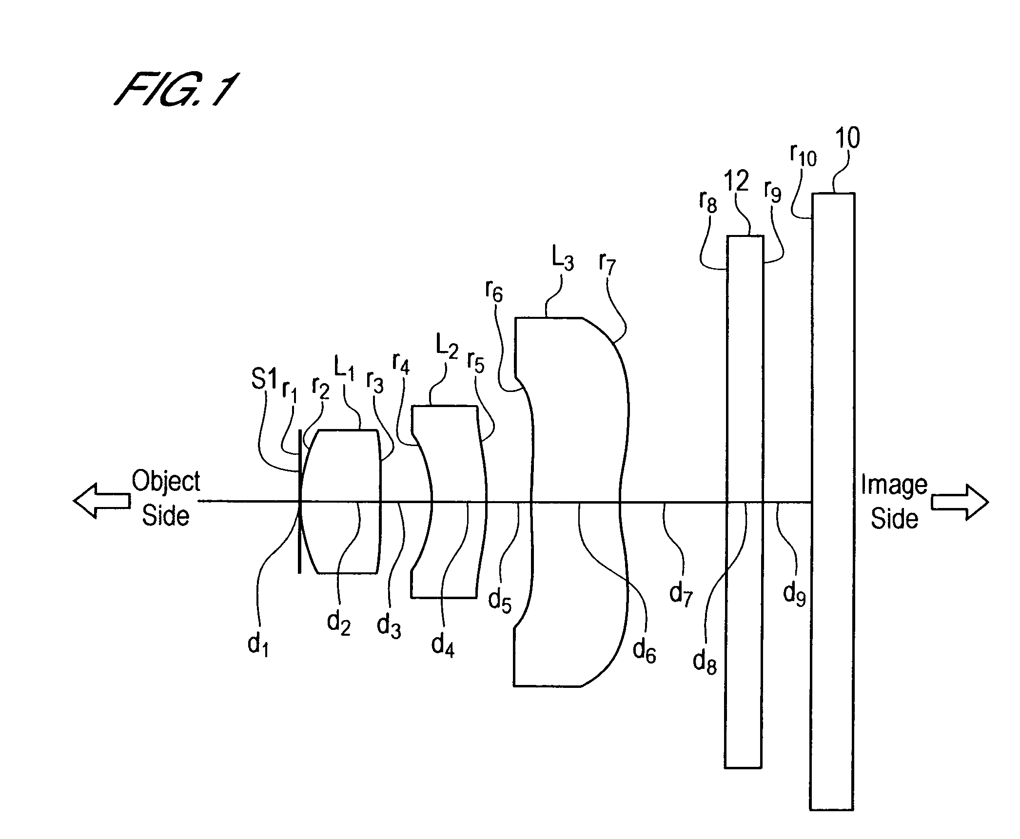
first embodiment
[0155]Zeonex E48R was used as the material of the first lens L1 and third lens L3, while polycarbonate was used as the material of the second lens L2.
[0156](A) The focal length f1 of the first lens L1 is f1=0.58 mm.
[0157](B) The object-side radius of curvature r2 of the first lens L1 is r2=0.297 mm.
[0158](C) The image-side radius of curvature r3 of the first lens L1 is r3=5.941 mm.
[0159](D) The interval D along the optical axis between the second lens L2 and the third lens L3 is d3=0.1020 mm.
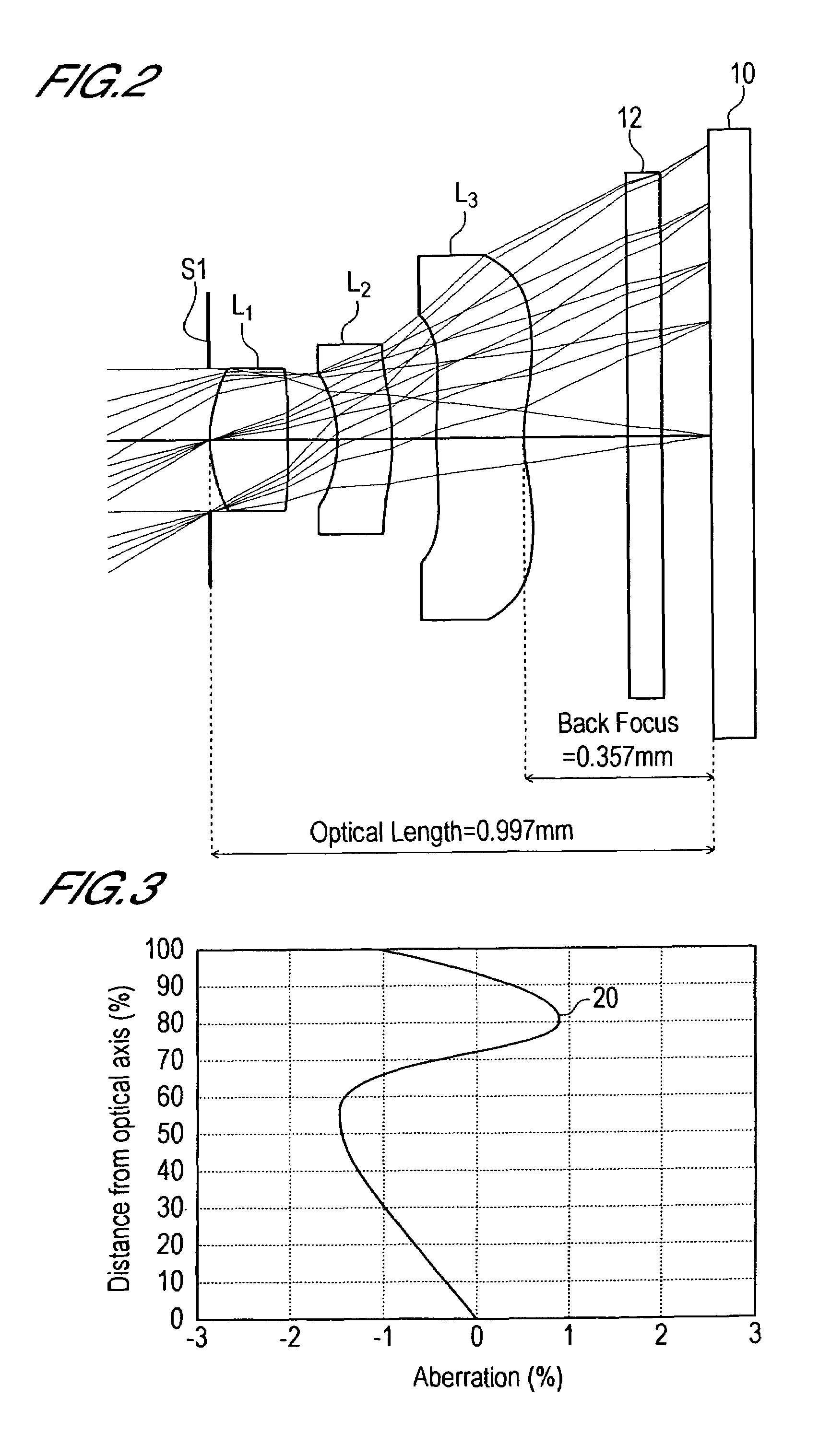
[0160](E) The optical length L is L=0.997 mm.
[0161](F) The image height (length of the diagonal line in the rectangular light-receiving area) 2Y is 2Y=1.18 mm.
[0162]Hence:
f1 / f=0.58 / 1.00=0.58 (1)
r2 / r3=0.297 / 5.941=0.0500 (2)
d3 / f=0.1020 / 1.00=0.1020 (3)
L / 2Y=0.997 / 1.18=0.8449 (4)
[0163]Hence the lens system of the first Embodiment satisfies each of the following condition equations (1) to (4).
0.57<f1 / f<0.65 (1)
0.01≦r2 / r3≦0.05 (2)
0.1≦d3 / f<0.15 (3)
0.6<L / 2Y<0.9 (4)
[0164]In the foll...
second embodiment
[0172]Zeonex E48R was used as the material of the first lens L1 and third lens L3, while polycarbonate was used as the material of the second lens L2.
[0173](A) The focal length f1 of the first lens L1 is f1=0.61 mm.
[0174](B) The object-side radius of curvature r2 of the first lens L1 is r2=0.323 mm.
[0175](C) The image-side radius of curvature r3 of the first lens L1 is r3=32.244 mm.
[0176](D) The interval D along the optical axis between the second lens L2 and the third lens L3 is d3=0.1108 mm.
[0177](E) The optical length L is L=1.042 mm.
[0178](F) The image height (length of the diagonal line in the rectangular light-receiving area) 2Y is 2Y=1.18 mm.
[0179]Hence:
f1 / f=0.61 / 1.00=0.61 (1)
r2 / r3=0.323 / 32.244=0.0100 (2)
d3 / f=0.1108 / 1.00=0.1108 (3)
L / 2Y=1.042 / 1.18=0.8831 (4)
[0180]Hence the lens system of the second Embodiment satisfies each of the following condition equations (1) to (4).
0.57f1 / f<0.65 (1)
0.01≦r2 / r3≦0.05 (2)
0.1≦d3 / f<0.15 (3)
0.6<L / 2Y<0.9 (4)
[0181]As shown in ...
third embodiment
[0188]Zeonex E48R was used as the material of the first lens L1 and third lens L3, while polycarbonate was used as the material of the second lens L2.
[0189](A) The focal length f1 of the first lens L1 is f1=0.62 mm.
[0190](B) The object-side radius of curvature r2 of the first lens L1 is r2=0.326 mm.
[0191](C) The image-side radius of curvature r3 of the first lens L1 is r3=20.315 mm.
[0192](D) The interval D along the optical axis between the second lens L2 and the third lens L3 is d3=0.1118 mm.
[0193](E) The optical length L is L=1.071 mm.
[0194](F) The image height (length of the diagonal line in the rectangular light-receiving area) 2Y is 2Y=1.20 mm.
[0195]Hence:
f1 / f=0.62 / 1.00=0.62 (1)
r2 / r3=0.326 / 20.315=0.0160 (2)
d3 / f=0.1118 / 1.00=0.1118 (3)
L / 2Y=1.071 / 1.20=0.8925 (4)
[0196]Hence the lens system of the third Embodiment satisfies each of the following condition equations (1) to (4).
0.57<f1 / f<0.65 (1)
0.01≦r2 / r3≦0.05 (2)
0.1≦d3 / f<0.15 (3)
0.6<L / 2Y<0.9 (4)
[0197]As shown ...
PUM
 Abstract
Description
Claims
Application Information