Capacitor having improved surface breakdown voltage performance and method for marking same

a capacitor and surface breakdown voltage technology, applied in the field of high-voltage capacitors, can solve the problems of achieve the effects of improving the high-voltage breakdown voltage performance, less overall effect, and increasing the surface breakdown voltag

Inactive Publication Date: 2010-02-23
MAXWELL JOHN
View PDF8 Cites 8 Cited by
  • Summary
  • Abstract
  • Description
  • Claims
  • Application Information

AI Technical Summary

Benefits of technology

[0023]Thus, in a second embodiment of the present invention, the laser mark is oriented so that a flat portion of the mark is is oriented closest to the adjacent terminal. For example, if the symbol is an asymmetrical letter such as “C”, “F”, or “L”, the long side of the symbol is oriented closest to the terminal. Thus, the registered mark for Johanson Dielectrics, Inc. is a single “J”. When the long side of the “J” is closest to the adjacent terminal, the high voltage breakdown voltage performance is better than when the small tip of the “J” is closest to the terminal.
[0024]Similarly, if the symbol is a symmetrical letter such as “A”, “H”, or “S”, then either long side of the symbol is oriented closest to the terminal. Although the symbol orientation by itself has less overall effect on the surface breakdown voltage, when used in combination with symbol location it substantially increases the surface breakdown voltage, thereby improving overall capacitor performance.

Problems solved by technology

More particularly, if the laser mark is oriented so that its largest portion is close to the terminal, an increase in surface breakdown voltage results.

Method used


Image

  • Capacitor having improved surface breakdown voltage performance and method for marking same
  • Capacitor having improved surface breakdown voltage performance and method for marking same
  • Capacitor having improved surface breakdown voltage performance and method for marking same

Examples


Embodiment Construction

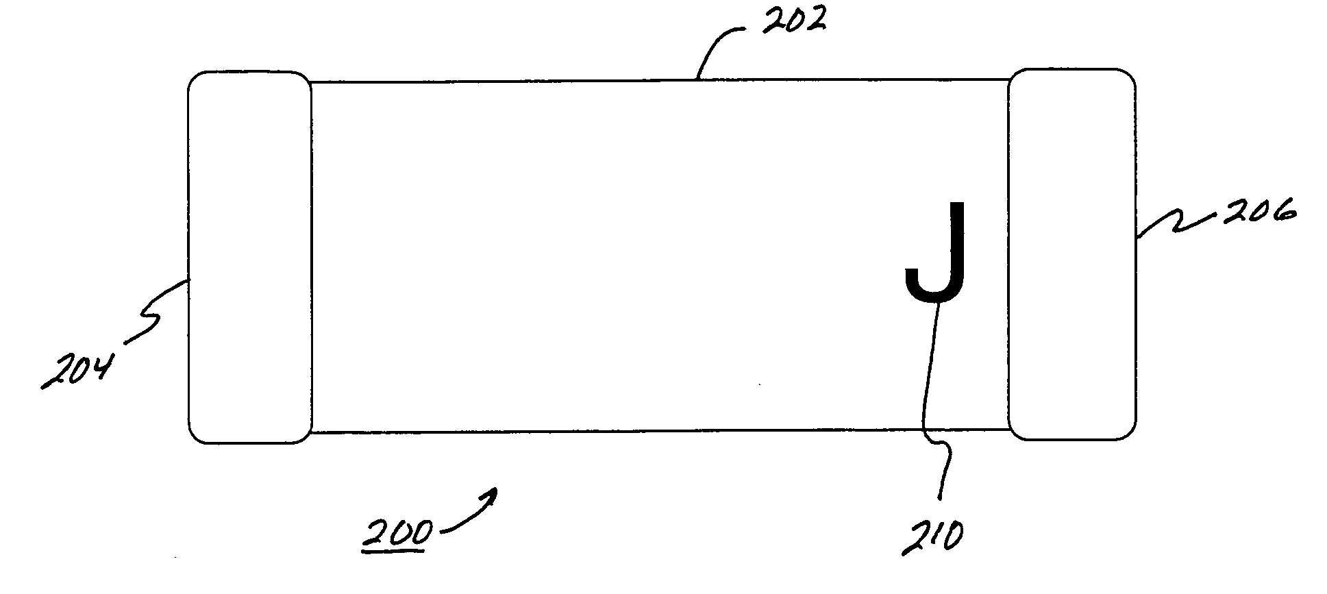
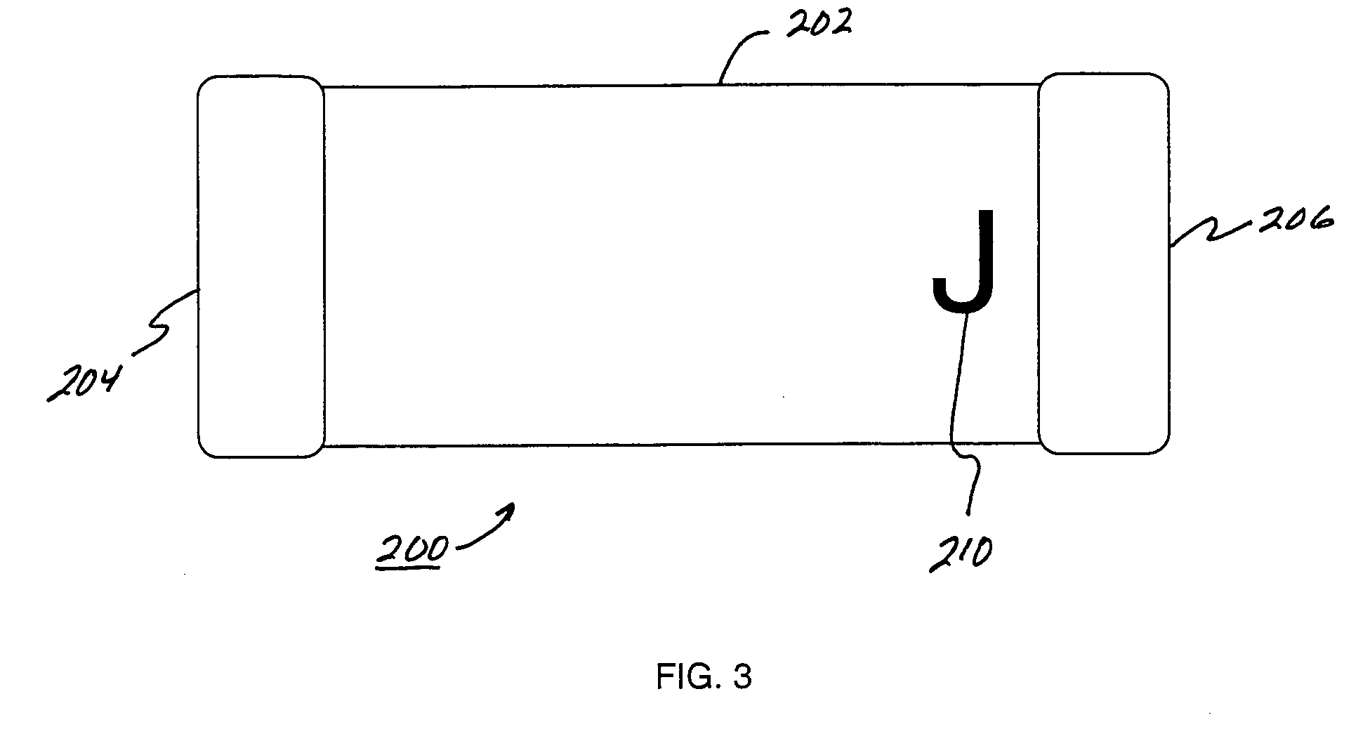
[0033]The following exemplary discussion focuses on a capacitor having improved surface breakdown voltage performance, and a novel method for applying laser marking which increases capacitor surface breakdown voltage.

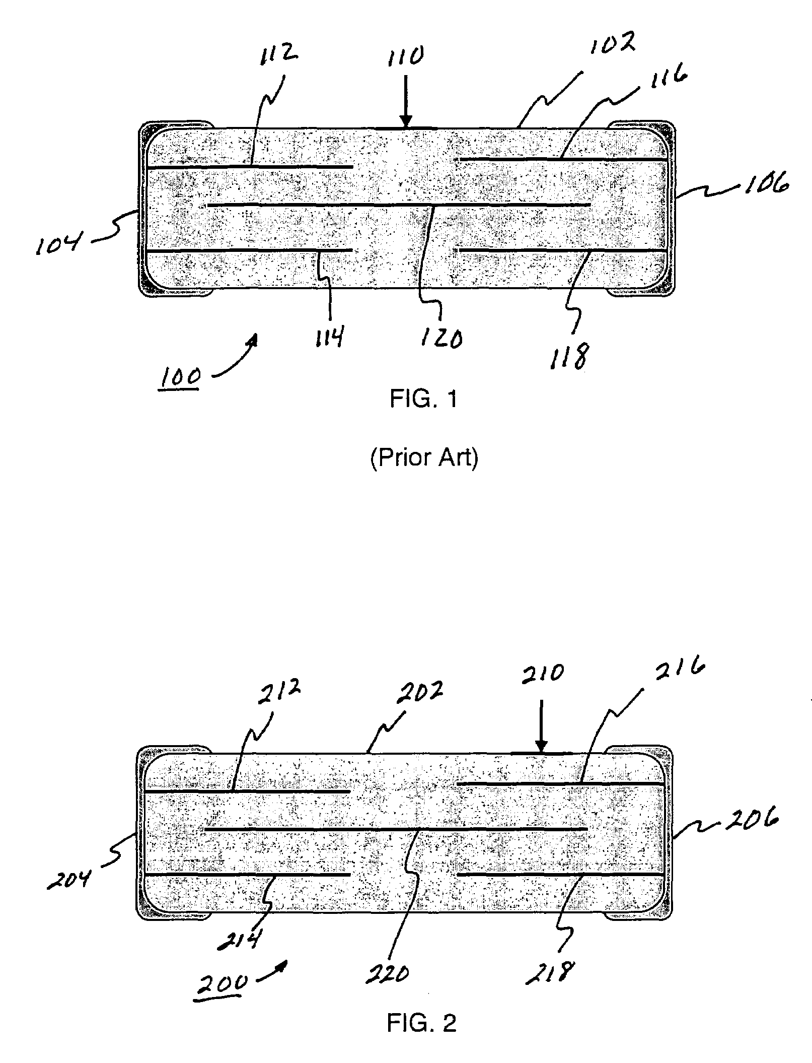
[0034]Referring to FIG. 1, the internal structure and marking of a prior art high-voltage capacitor 100 is shown. Capacitor 100 is comprised of a ceramic body or dielectric 102, terminals 104 and 106 connected to opposite ends of dielectric 102, and control electrodes 112-114 and 116-118 positioned within dielectric 102 and connected to terminals 104 and 106, respectively. Capacitor 100 further comprises a floating electrode 120 positioned within dielectric 102 between control electrodes 112-114 and 116-118. A laser mark 110 is positioned on the top outer surface of dielectric 102, equidistant between terminals 104 and 106.

[0035]As will be apparent to those skilled in the art, the inclusion of the laser mark 110 equidistant between terminals 104 and 106 can reduce the s...


PUM


Abstract

A capacitor having improved surface breakdown voltage performance and a method for applying laser marking to capacitors which does not reduce capacitor surface breakdown voltage, can be applied using existing laser marking technologies and apparatus, and which results in a mark that is legible and clear, is disclosed. In a first exemplary embodiment a capacitor includes a laser mark which is located near one of the capacitor terminals. The exact location is not critical as long as the mark does not make physical contact with the terminal. Conventional laser marking technologies and apparatus may be used to fix the mark in the new location. In a second embodiment the laser mark is oriented so that a flat portion of the mark is is oriented closest to the adjacent terminal.

Description

BACKGROUND OF THE INVENTION[0001]1. Field of the Invention[0002]The present invention relates to high-voltage capacitors and, more particularly, to a capacitor having improved surface breakdown voltage performance using novel method for applying laser or conductive ink marking which increases capacitor surface breakdown voltage.[0003]2. Description of the Prior Art[0004]Capacitors are second only to resistors as electronic circuit elements and are used in virtually every type of electronic circuit. In a typical application, capacitors are used as coupling capacitors in electronic circuits to block a direct current (DC) voltage while allowing alternating current (AC) currents to pass. They are also used as bypass capacitors to prevent the voltage at a circuit node from changing. These two applications do not depend on the exact value of the capacitance. In other applications, capacitors are also used in inductor-capacitor (LC) resonant circuits, in resistor-capacitor (RC) bridges, an...

Claims


Application Information

Patent Timeline
Patent Type & Authority Patents(United States)
IPC IPC(8): H01G4/228
CPCH01G2/24H01G4/35H01G4/30
Inventor MAXWELL, JOHN
Owner MAXWELL JOHN
Why Eureka
Try Eureka