Infrared detector and process for fabricating the same

a technology of infrared detectors and fabrication processes, applied in the field of infrared detectors, can solve the problems of adding an additional fabrication cost, and achieve the effects of reducing cost, reliable output, and optimum performan

Inactive Publication Date: 2010-03-02
MATSUSHITA ELECTRIC WORKS LTD
View PDF11 Cites 7 Cited by
  • Summary
  • Abstract
  • Description
  • Claims
  • Application Information

AI Technical Summary

Benefits of technology

[0003]In view of the above problem, the present invention has been accomplished to provide an infrared detector which is capable of being fabricated at a reduced cost, yet assuring optimum performance. The infrared detector in accordance with the present invention includes a circuit block carrying an infrared sensor element and electronic components, and a case enclosing the circuit block. The circuit block is composed of a dielectric resin layer and a first substrate which is formed with a circuit pattern for mounting the electronic components. The dielectric resin layer is formed in its top with a recess which defines around its periphery with a shoulder for supporting opposite ends of the infrared sensor. The recess defines a thermal insulation space below the infrared sensor to give a reliable output without being adversely affected by heat developed at the electronic components. The feature of the present invention resides in that the first substrate is integrated to the lower end of the dielectric resin layer with at least one of the electronic components being molded into the dielectric resin layer below the recess to make the circuit block of a unified mold structure. Thus, a substantial part or all of the electronic components can be molded into the dielectric layer to realize the circuit block of a simple and low profile structure, while retaining an advantage of keeping the infrared sensor element sufficiently away from the electronic components and an associated electronic circuit, thereby assuring to give the infrared detector which is simple in construction, economical in cost, and reliable in the infrared detection.
[0013]The base carries the terminal pins composed of a power supply terminal pin, a ground terminal pin, and a signal output terminal pin all extending through the base. At least one of the terminal pins extends through the circuit block for electrical connection with lands which are formed on top of the first resin layer to mount the infrared sensor element. In this instance, one or more of the terminal pins can be bonded on top of the circuit block for easy electrical connection.
[0014]Preferably, a top shield projects on top of the circuit block in order to electrically shield the infrared sensor element from at least one of the power supply terminal pins and the signal output terminal pin, thereby protecting the infrared sensor element from receiving undesired electrical signal transmitted through the terminal pins and therefore assuring reliable infrared radiation at the infrared sensor element.
[0015]The top shield may be configured to have its lower end embedded into the top end of the circuit block to give an improved shield effect of shielding over a wide range from within the circuit block.
[0018]The top shield may be formed on an end wall of the first resin layer so that it can be easily realized in the form of a deposited layer on the end wall.

Problems solved by technology

Also for electrical connection of the infrared sensor element to the electronic components, the three-dimensional circuit block has to incorporate a correspondingly complicated circuit pattern or conductors, thereby adding an additional fabrication cost.

Method used


Image

  • Infrared detector and process for fabricating the same
  • Infrared detector and process for fabricating the same
  • Infrared detector and process for fabricating the same

Examples


Embodiment Construction

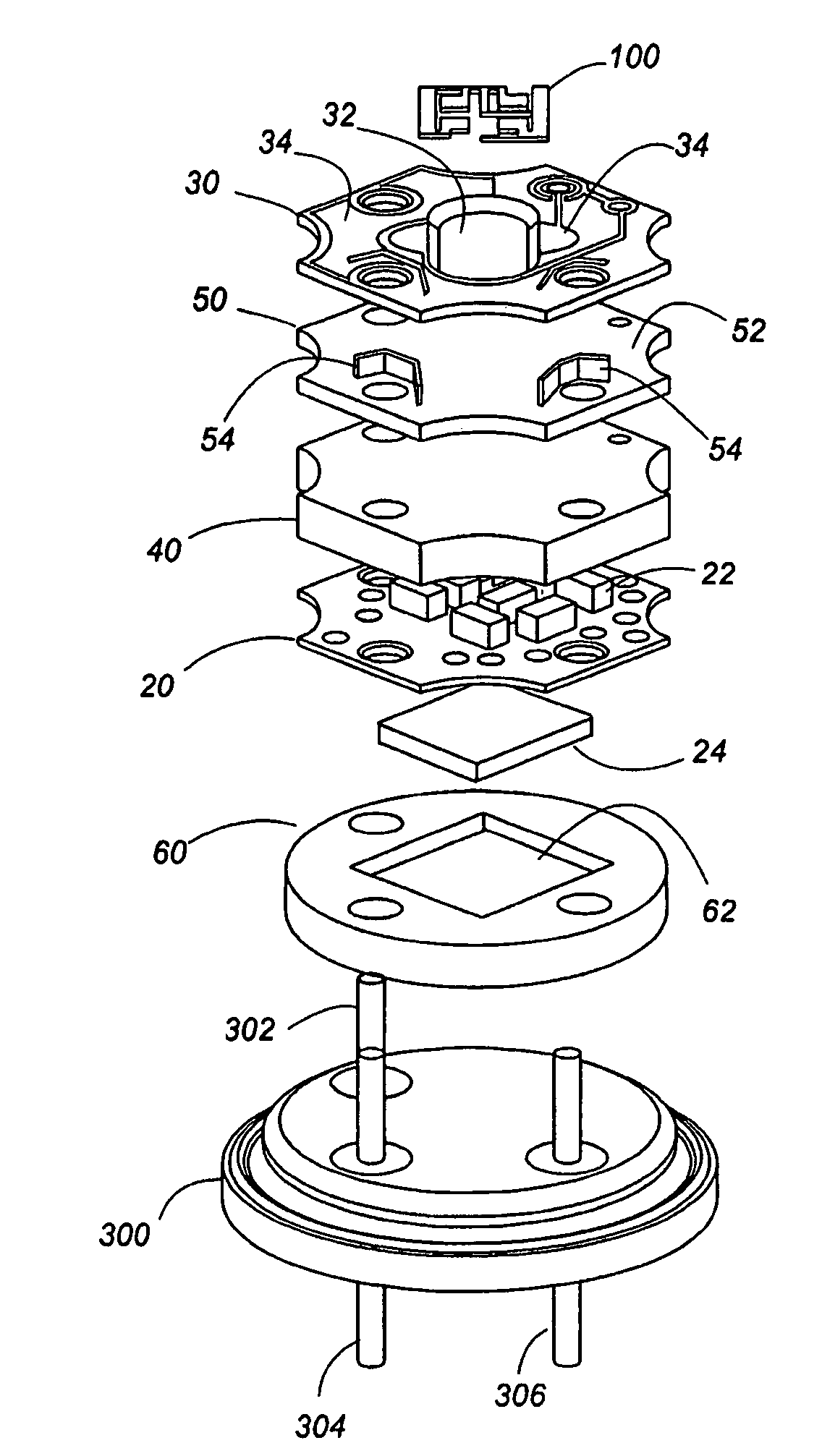
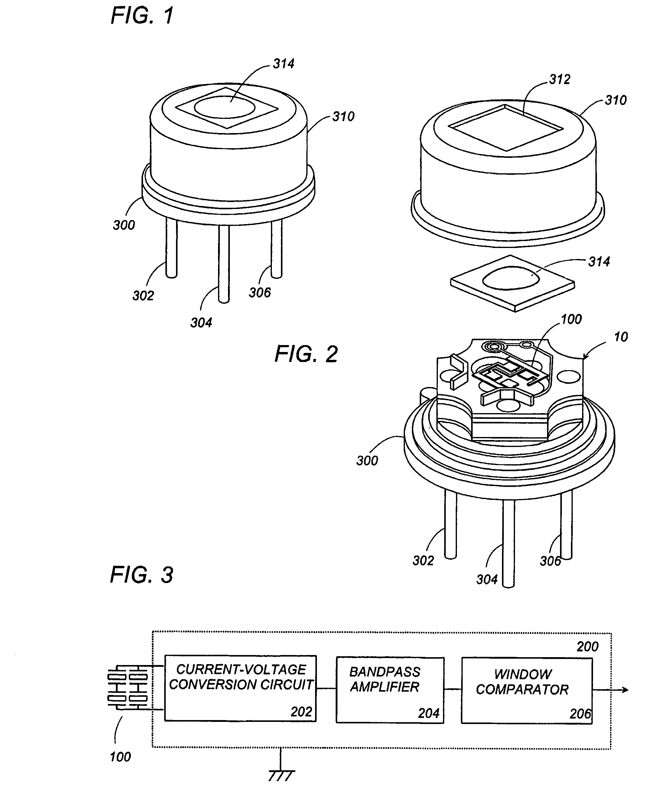
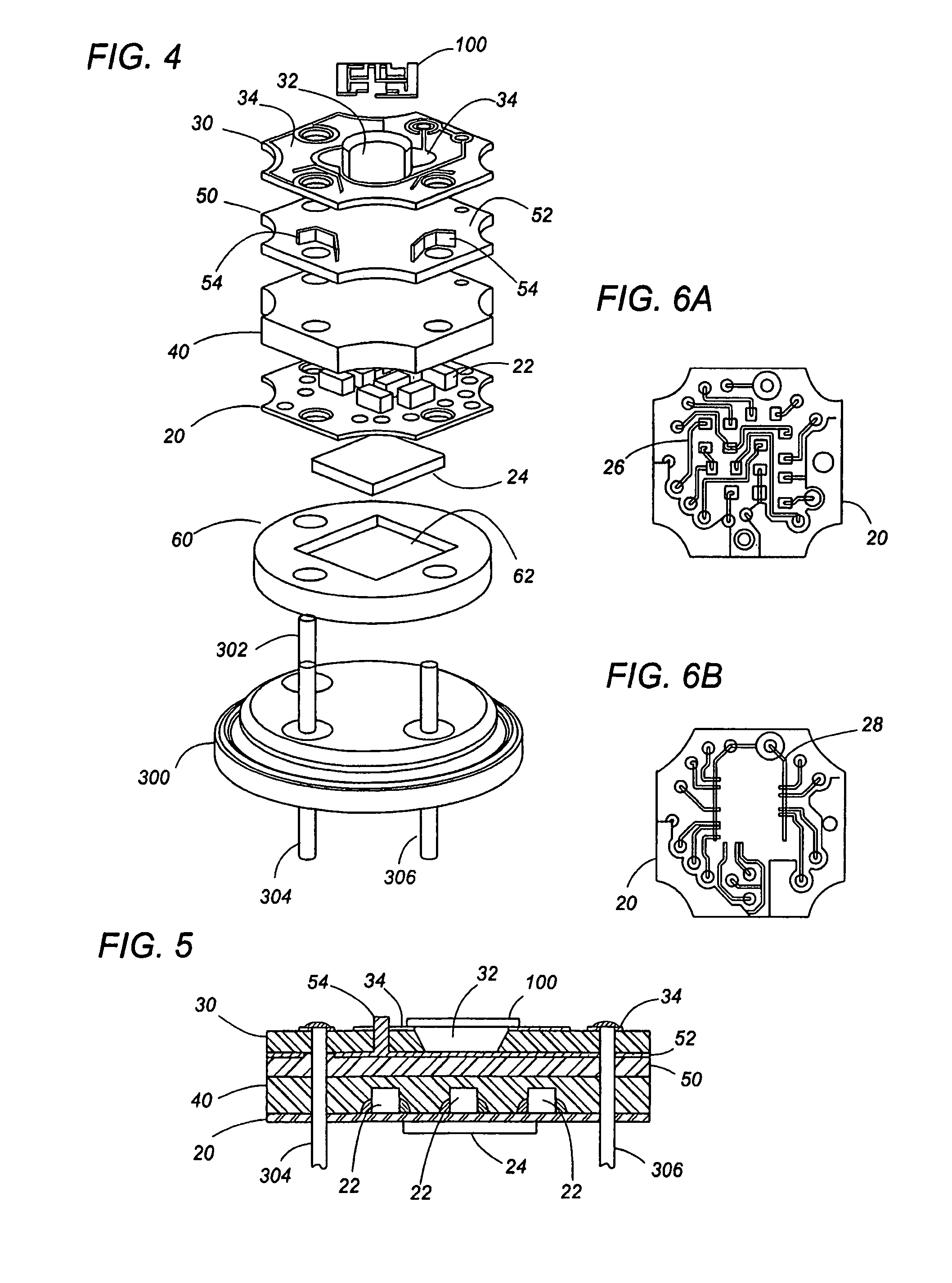
[0038]Referring now to FIGS. 1 to 3, there is shown an infrared detector unit in accordance with a first embodiment of the present invention. The infrared detector is designed to determine a presence of an object or human body emitting an infrared radiation, and includes circuit block 10 carrying a thermal infrared sensor element 100 and a signal processing circuit 200 which is configured to receive a sensor output from the sensor element 100 to analyze the amount of the infrared radiation received at the sensor element for determination of the presence of the object. The infrared sensor element 100 provides a minute electric current in the order of several picoamperes, which is amplified about 4000 times in the signal processing circuit 200 to give an output signal indicative of the presence of the object. The signal processing circuit 200 is realized by electronic components and, as shown in FIG. 3, includes a current-voltage conversion circuit 202 for conversion of the sensor out...


PUM


Abstract

An infrared detector includes a circuit block carrying an infrared sensor element and electronic components. The circuit block is composed of a dielectric resin layer and a first substrate formed with a circuit pattern and mounting the electronic components. The dielectric resin layer is formed in its top with a recess which defines around its periphery with a shoulder for supporting opposite ends of the infrared sensor. The first substrate is integrated to the lower end of the dielectric resin layer with at least one of the electronic components being molded into the dielectric resin layer to make the circuit block of a unified mold structure. Thus, a part or all of the electronic components are molded into the dielectric layer to realize the circuit block of a simple and low profile structure, while retaining an advantage of keeping the infrared sensor element sufficiently away from the electronic components and an associated electronic circuit, thereby assuring to give the infrared detector which is simple in construction, economical in cost, and reliable in the infrared detection.

Description

TECHNICAL FIELD[0001]The present invention is directed to an infrared detector, more particularly to an infrared sensor including an infrared sensor element and an associated electronic circuit commonly mounted on a single circuit block, and a process of fabricating the infrared detector.BACKGROUND ART[0002]WO 2004 / 00198 A1 discloses a prior infrared detector which comprises a circuit block carrying an infrared sensor element, and a case accommodating therein the circuit block. The circuit block is prepared as an injection molded plastic body or so-called molded interconnect device (MID) for mounting, in addition to the infrared sensor element, various electronic components constituting a signal processing circuit which provides a detection output. In order to make the infrared detector compact, i.e., to arrange various electronic components within a limited space, the circuit block is specifically designed into a rather complicated three-dimensional shape in correspondence with the...

Claims


Application Information

Patent Timeline
Patent Type & Authority Patents(United States)
IPC IPC(8): G01J5/20
CPCG01J1/02G01J1/0204H01L31/0203G01J2001/0276H05K1/0218H05K1/185
Inventor NISHIKAWA, TAKAYUKISUMI, SADAYUKIKAMITSU, TOMOHIROTANIGUCHI, RYOHIRATA, MASAYASATO, SHIN
Owner MATSUSHITA ELECTRIC WORKS LTD
Why Eureka
Try Eureka