
High frequency acousto-optic frequency shifter having wide acceptance angle

a frequency shifter and wide acceptance angle technology, applied in the field of acoustooptic frequency shifters, can solve the problems of large frequency shift, >100 mhz, and insufficient efficiency of the frequency shift process, and achieve the effect of wide bandwidth and easy design and matching

Active Publication Date: 2010-03-23
GOOCH & HOUSEGO
View PDF3 Cites 4 Cited by
  • Summary
  • Abstract
  • Description
  • Claims
  • Application Information

AI Technical Summary

Benefits of technology

"The present invention is about an acousto-optic (AO) frequency shifter that uses an anisotropic crystal and an acoustic transducer to shift the frequency of an optical beam. The AO frequency shifter has been designed to meet the parallel tangents condition, which ensures that the acoustic wave and the optical beam have the same group velocity at the same angle of incidence. The AO frequency shifter has been found to have a high degree of acoustic attenuation, which makes it difficult to achieve the desired frequency shift. The invention proposes a solution to this problem by using a narrowband transducer with a fractional bandwidth of less than 15 degrees to absorb the acoustic power emanating from the transducer and reduce the acoustic power loss. The invention also proposes a method for simultaneously diffracting both optical beams in the same direction to produce two frequency-shifted beams with equal amounts of e and o polarizations. The anisotropic crystal used in the AO frequency shifter can be TeO2, and the system can operate in a polarization independent condition to obtain two simultaneous output optical beams."

Problems solved by technology

If this condition is not met, then significant ambiguity regarding the velocity of the remote surface will be introduced, and the signal processing will not be able to correct the situation, giving rise to erroneous results.
Because the frequency shifting process is not 100% efficient, a small amount of the residual incident beam (unshifted “zero degree” beam) also exits the Bragg cell device through the second (output) aperture.
There are well known problems relating to producing a large frequency shift (e.g. >100 MHz) using a conventional AOM.
The angular tolerance with which the laser beam may deviate from this condition in the standard (40 or 80 MHz) devices is small if they are to continue working efficiently, generally of the order of tens of milli-radians, and this makes alignment difficult.
This means that any divergence or beam misalignment in excess of this value will cause a noticeable drop in efficiency of the device.
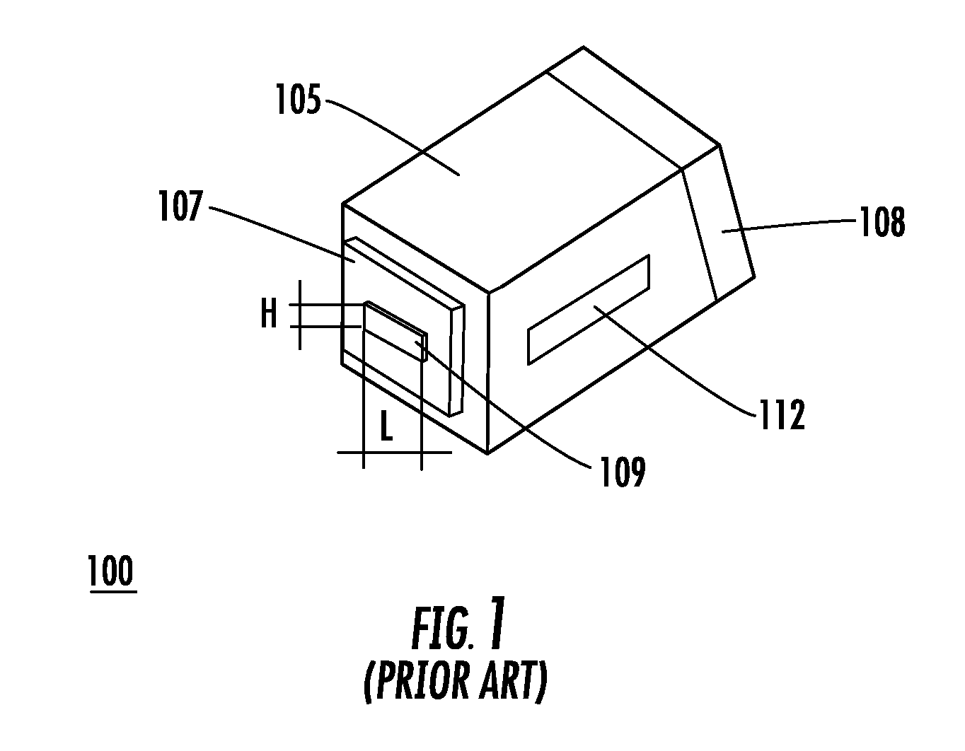
However, if the transducer L is shortened (e.g. make L<10 mm) in an attempt to increase the angular acceptance given by equation (1), another problem arises, specifically, the inability to maintain diffraction efficiency at the previous value.
However, more RF power will be needed to drive the shorter device in order to maintain a given level of efficiency, also it is possible that the acoustic divergence from this shorter transducer will become excessively large, in which case the operation of the device will tend to move out of the “Bragg regime” and into the “Raman-Nath” regime of diffraction, which is known to be undesirable for a device of this type as multiple diffracted orders are produced, of which only a single one is useful, and thus efficiency is lowered.
More RF power can also cause excessive heating of the transducer, and the resulting temperature rise of the AO interaction crystal (which is in direct physical contact with the transducer), which can significantly alter its optical properties.
This unwanted effect would include the formation of a refractive index gradient, which will tend to steer and distort the outgoing beam.
If the objective is to launch the output beam into a single mode optical fiber (as is the case with most sensors described herein), these effects will adversely affect the efficiency with which light couples into the core of the output fiber.
This will contribute to further reductions in overall efficiency of the AOM-based frequency shifting system.
Conventional AO frequency shifters producing this amount of frequency shift by means of a single diffracted output beam are generally impossible because of the high degree of acoustic attenuation of the acoustic wave.

Method used


Image

  • High frequency acousto-optic frequency shifter having wide acceptance angle
  • High frequency acousto-optic frequency shifter having wide acceptance angle
  • High frequency acousto-optic frequency shifter having wide acceptance angle

Examples


examples

[0066]It should be understood that the Examples described below are provided for illustrative purposes only and do not in any way define the scope of the invention.

[0067]FIG. 11 is a schematic diagram of a dual polarization AO frequency shifter 1100 according to an embodiment of the present invention designed for minimum acoustic attenuation which includes an acoustic absorber 1120, found to provide good performance. The prototype AO frequency shifter 1100 was fabricated for use in a laser Doppler velocimetry (LDV) system. In order to make room for acoustic absorber 1120, the transducer 1115 was located away from the output face of the TeO2 crystal so as to allow for the walk-off of the acoustic beam. The transducer electrodes are not shown.

[0068]When AO frequency shifter 900 shown in FIG. 9 was tested, all aspects of the performance measured were in accordance with the design calculations / simulations, i.e. simultaneous dual-polarization (e and o polarization) diffraction occurred a...


PUM

PropertyMeasurementUnit
frequencyaaaaaaaaaa
frequencyaaaaaaaaaa
frequencyaaaaaaaaaa

Abstract

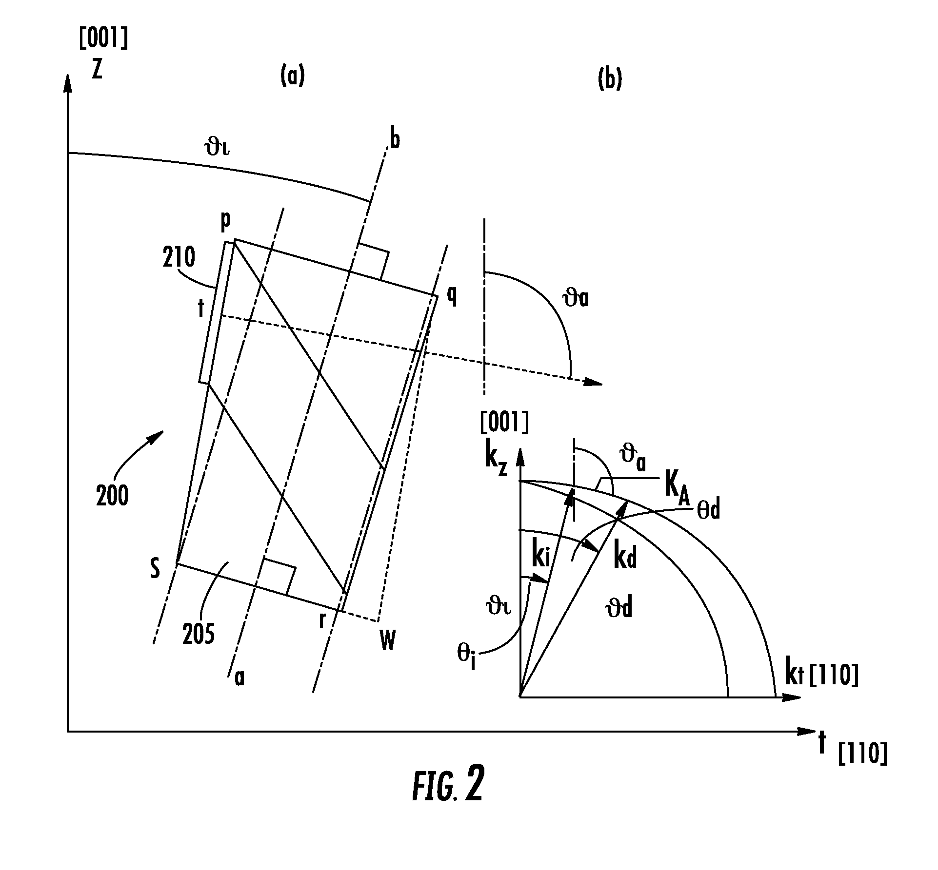
An acousto-optic (AO) frequency shifter includes an anisotropic crystal having an optical axis and an input face, and an acoustic transducer having electrodes affixed to the face for receiving an electrical signal and projecting an acoustic wave into the crystal. The anisotropic crystal is cut relative to the face so that the transducer is at an acoustic angle (θa) corresponding to a predetermined angle of incidence (θi) of an optical beam to be directed relative to the optic axis of the anisotropic crystal to substantially satisfy the parallel tangents phase matching condition.

Description

FIELD OF THE INVENTION[0001]The present invention relates to acousto-optic frequency shifters, which are also sometimes referred to as frequency translators.BACKGROUND OF THE INVENTION[0002]Lasers are used in a wide variety of optical sensors. The natural frequency of a laser depends on the lasing medium and the cavity optics. However, once these parameters are chosen, the emission frequency is fixed and frequency stability of the laser beam is generally very good. Thus, in a conventional Helium-Neon laser a common wavelength of operation is 632.8 nm, corresponding to a frequency of 4.7408×10¹⁴ Hz. In a typical application, a pair of beams is derived from a single laser (for example using a beam-splitter), and the frequency of one of these beams is shifted by a fixed amount, such as in the tens or hundreds of MHz, as an aid to signal processing in an optical sensor-based system.[0003]In a typical optical sensor-based system, such as a laser velocimeter or laser vibrometer, one of th...

Claims


Application Information

Patent Timeline
Patent Type & Authority Patents(United States)
IPC IPC(8): G02F1/33
CPCG02F1/11G02F1/353G02F1/3544G02F2001/3542G02F2201/17G02F1/3542
Inventor PANNELL, CHRISTOPHER N.WARD, JONATHAN DAVID
Owner GOOCH & HOUSEGO
Learn More