

Method for producing ceramic honeycomb filter
a technology of ceramic honeycomb and filter, which is applied in the field of ceramic honeycomb filter, can solve the problems of increasing engine power, reducing engine pressure loss, and reducing the ability of high exhaust gas temperature to combust pm, and reducing the elastic decrease of particulate-matter capture function
- Summary
- Abstract
- Description
- Claims
- Application Information
AI Technical Summary
Benefits of technology
Problems solved by technology
Method used
Image

Examples
example 1
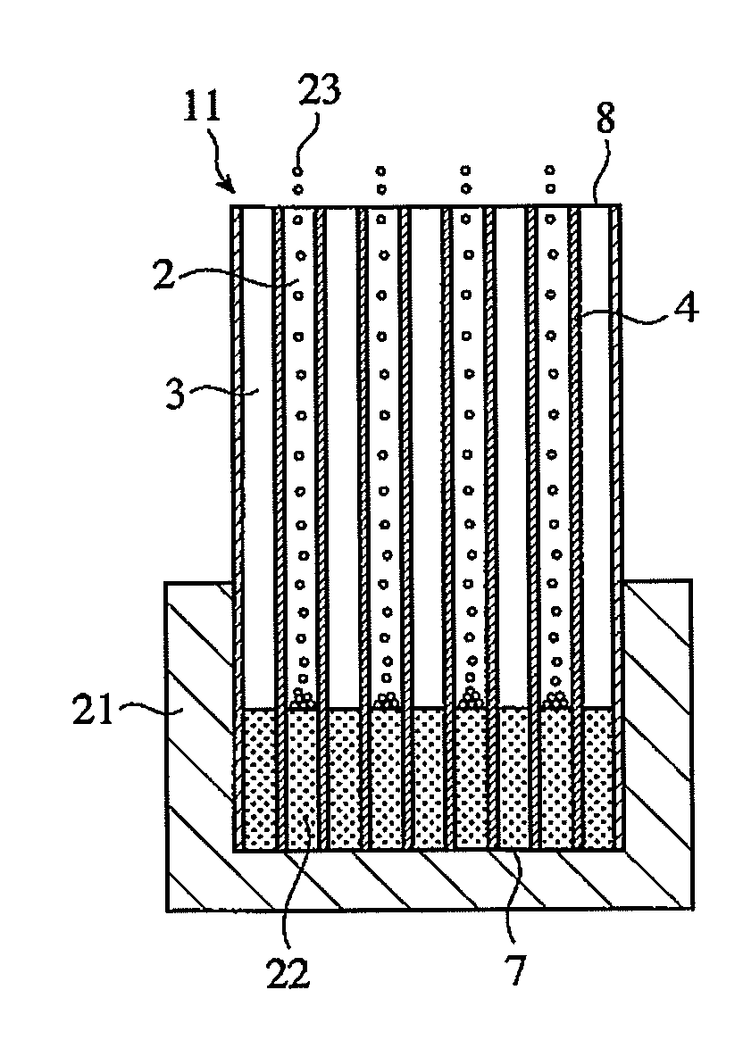
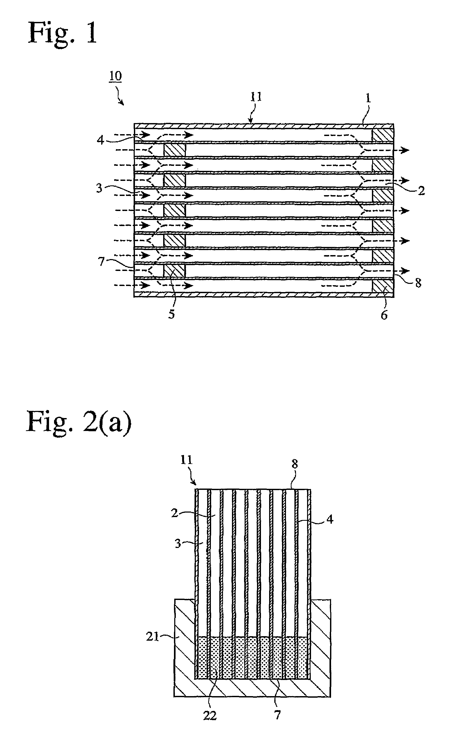
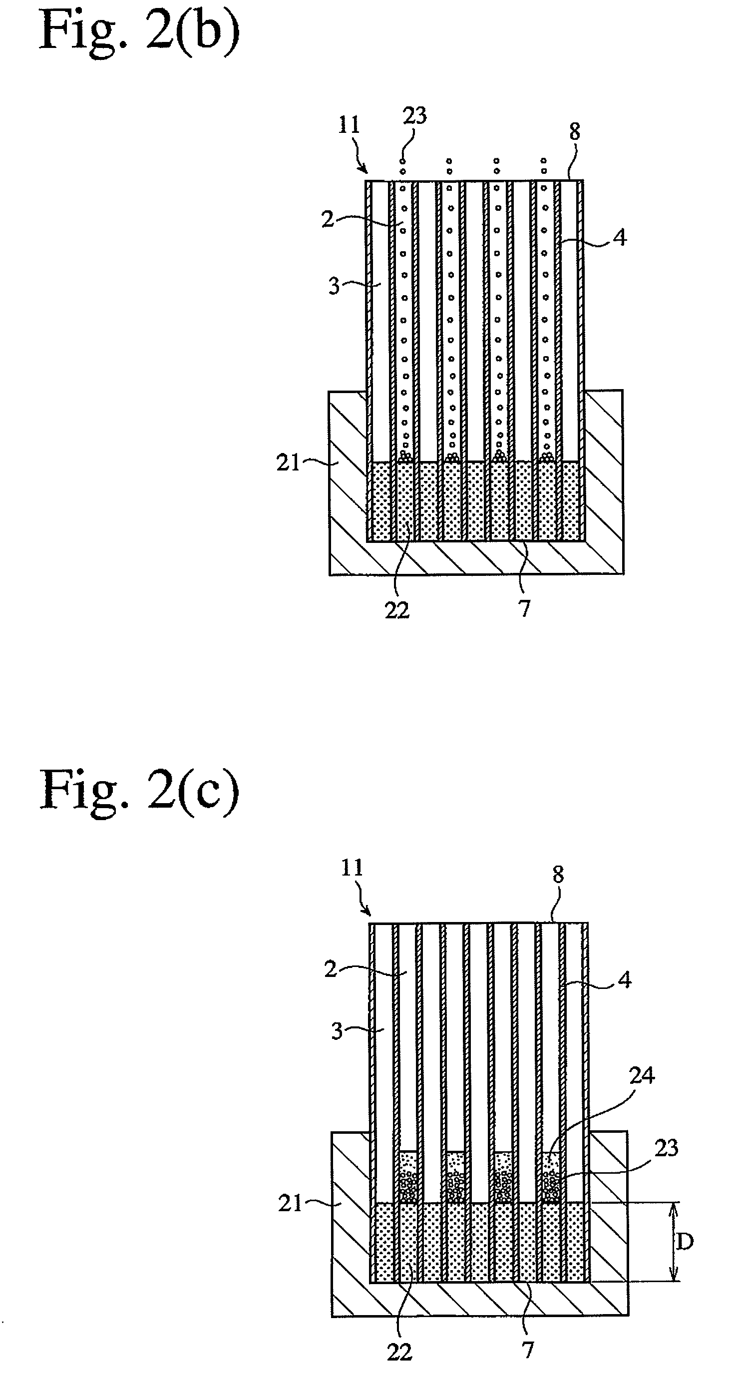
[0050]As shown in FIG. 1, a honeycomb filter 10 having large numbers of rectangular-cross-sectioned flow paths 2, 3 partitioned by cell walls 3 inside a peripheral wall 1, the end portions 7, 8 of the flow paths 2, 3 being sealed by plugs 5, 6 in a checkerboard pattern, and the plugs 5 being located in the flow paths at positions separate from the inlet-side end surface 7 was produced by the flowing steps.
[0051]Kaolin powder, talc powder, silica powder and alumina powder were mixed to provide a powdery cordierite-forming material having a composition comprising 50% by mass of SiO2, 35% by mass of Al2O3 and 15% by mass of MgO. After this powdery cordierite-forming material was mixed with methylcellulose and hydroxypropylmethylcellulose as a binder, and graphite particles as a lubricant and a pore-forming material, water was added, and full blending was conducted to produce a moldably plasticized ceramic material. This moldable ceramic material was extruded and cut to obtain a honeyco...
example 2
[0055]A cordierite honeycomb filter 10 was produced in the same manner as in Example 1, except that after changing an aqueous surfactant solution into the flow paths 2, ceramic granules were uniformly introduced while giving vibration of 100 Hz for 20 seconds to the honeycomb structure 11. By this method, plugs 5 were surely formed in the flow paths of the ceramic honeycomb structure at positions separate from the end surface in a short period of time.
example 3
[0056]A cordierite honeycomb filter 10 was produced in the same manner as in Example 1, except for using capsules (outer diameter: 1.0 mm, skin layer thickness: 100 μm) containing aqueous cordierite powder slurry as a plug-forming material in a skin layer and an oily, protective, inner layer, and heating the honeycomb structure 11 at 150° C. without using a filling accelerator to melt the capsules to permit the slurry to enter the flow paths. By this method, plugs were surely formed in the flow paths of the ceramic honeycomb structure at positions separate from the end surface in a short period of time.
PUM
| Property | Measurement | Unit |
|---|---|---|
| viscosity | aaaaa | aaaaa |
| outer diameter | aaaaa | aaaaa |
| particle size | aaaaa | aaaaa |
Abstract
Description
Claims
Application Information