Fiber laser based directional infrared countermeasure (DIRCM) system

a technology of directional infrared countermeasure and fiber laser, which is applied in the field of jamming systems, can solve the problems of not being able to successfully carry out the designated mission, the dircm system known today is subject to, and the threat of surface to air missiles by now a common threa

Active Publication Date: 2010-03-30
EL OP ELECTRO OPTICS INDS
View PDF16 Cites 49 Cited by
  • Summary
  • Abstract
  • Description
  • Claims
  • Application Information

AI Technical Summary

Benefits of technology

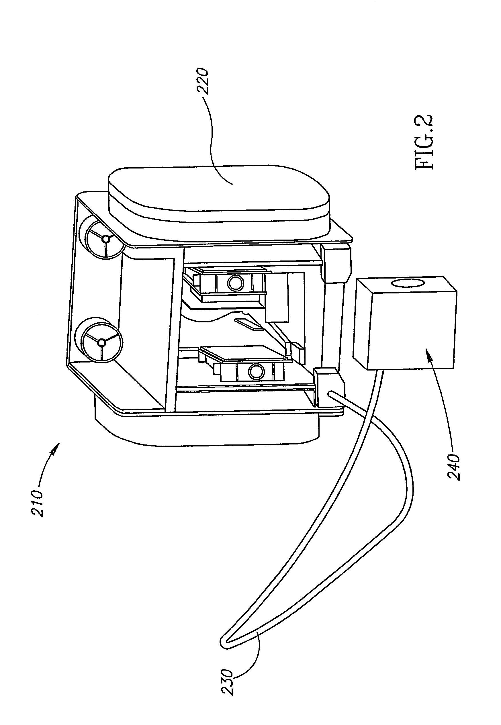
[0011]The present invention may include features that provide solutions that help alleviate at least the difficulties inherent in the cited DIRCM systems discussed above. This may be achieved, according to some embodiments of the present invention, by implementing a Fiber Laser means in the DIRCM system.
[0012]Using a fiber laser means, according to some embodiments of the present invention, may enable improved operation characteristics to the tracking and jamming task. For example, the fiber laser means may provide high system efficiency while reducing energy losses in the mobile platform in which it is installed, may facilitates the chore of packaging the system into the limited available free space in the mobile platform that may carry it, may facilitate the adjustments of the optical components in the laser beam routing system, may prevent exposure to optical problems that in other systems may result from the platforms movements and ensuing vibrations and shock, may require relatively few optical components as compared to existing non-fiber laser systems, and / or may provide a more rigid and stable optical unit, and less electrical power and cooling requirements, due to the higher efficiency of the fiber lasers.

Problems solved by technology

The continuing development of ever more lethal and sophisticated homing heads relying on reception of the heat radiation emanated by motorized moving platforms (for example, aircraft, vehicles, armored vehicles, ships, etc.) highly endanger these transportation means that are exposed to the heat sensitive homing missiles, as all these means are inherently sources of radiated heat.
Thus for example, surface to air missiles are by now a common threat.
The DIRCM systems known today are subject to many disadvantages that may result from the inherent constraints due to the platforms' limitations, namely space, weight, and environmental conditions dictated by the platform on which the system is installed.
In other words, the DIRCM system is often integrated in a closed structure that may be exposed to probably very unfavorable environmental conditions, that may be far from optimal for successfully carrying out the designated mission.
Such a turret, for enabling monitoring of the approaching missile, may be subject to disturbances and constraints, such as the movement of the plane including change of course, shocks, vibrations, etc., making the optimal tracking maneuvers rather tedious if at all executable.
Naturally, such elements are complex and sensitive to shocks and vibrations, in such a way that may cause beam intensity and quality loses.
Such a system may be required to have the capability to exploit limited accessible and available free spaces in carrying platforms.

Method used


Image

  • Fiber laser based directional infrared countermeasure (DIRCM) system
  • Fiber laser based directional infrared countermeasure (DIRCM) system
  • Fiber laser based directional infrared countermeasure (DIRCM) system

Examples


first embodiment

[0105]There may be multiple embodiments of the quarter waveplate 1245. A first embodiment may be of a quarter waveplate for only the pump. The signal and idler are unspecified. The signal and idler may rotate at unspecified angles, which may tend to decrease the efficiency since the phases may not be aligned with the pump.

second embodiment

[0106]A second embodiment may be of a quarter waveplate for the pump and the signal and idler. This is the same case as a two independent OPOs with a single pass pump beam. This design may be more suitable for high-energy pulses that may only need one pass through the crystal to experience high conversion efficiency. The quarter waveplate may be replaced with a periscope or a babinet compensator if the OPO is a ring cavity. These elements make a half-wave rotation.

third embodiment

[0107]A third embodiment may be a quarter waveplate for the pump, and half-wave plate (any integer multiple) for the signal and the idler. In this case, the pump polarization may be rotated 90 degrees on each round trip, and the signal and idler polarizations may not be rotated. In this way, different polarization states of the pump may amplify the same polarization states of the signal and idler.

[0108]As mentioned above, any professional skilled in the art will appreciate the fact that this OPO is relatively simple to align and contains only one crystal.

[0109]Reference is now made to FIG. 13. In this embodiment, the OPO 1310 uses the different pump polarizations to amplify the same signal and idler. Pump beam 1320 may be incident on a dichroic mirror 1330 (“M3”) which may reflect the beam into OPO 1310. Pump beam 1320 may enter at mirror 1340 (“M1”). One polarization state of the pump is converted within nonlinear crystal 1350. The other polarization may pass through the crystal, a...


PUM

PropertyMeasurementUnit
wavelength bandaaaaaaaaaa
wavelengthsaaaaaaaaaa
wavelengthaaaaaaaaaa

Abstract

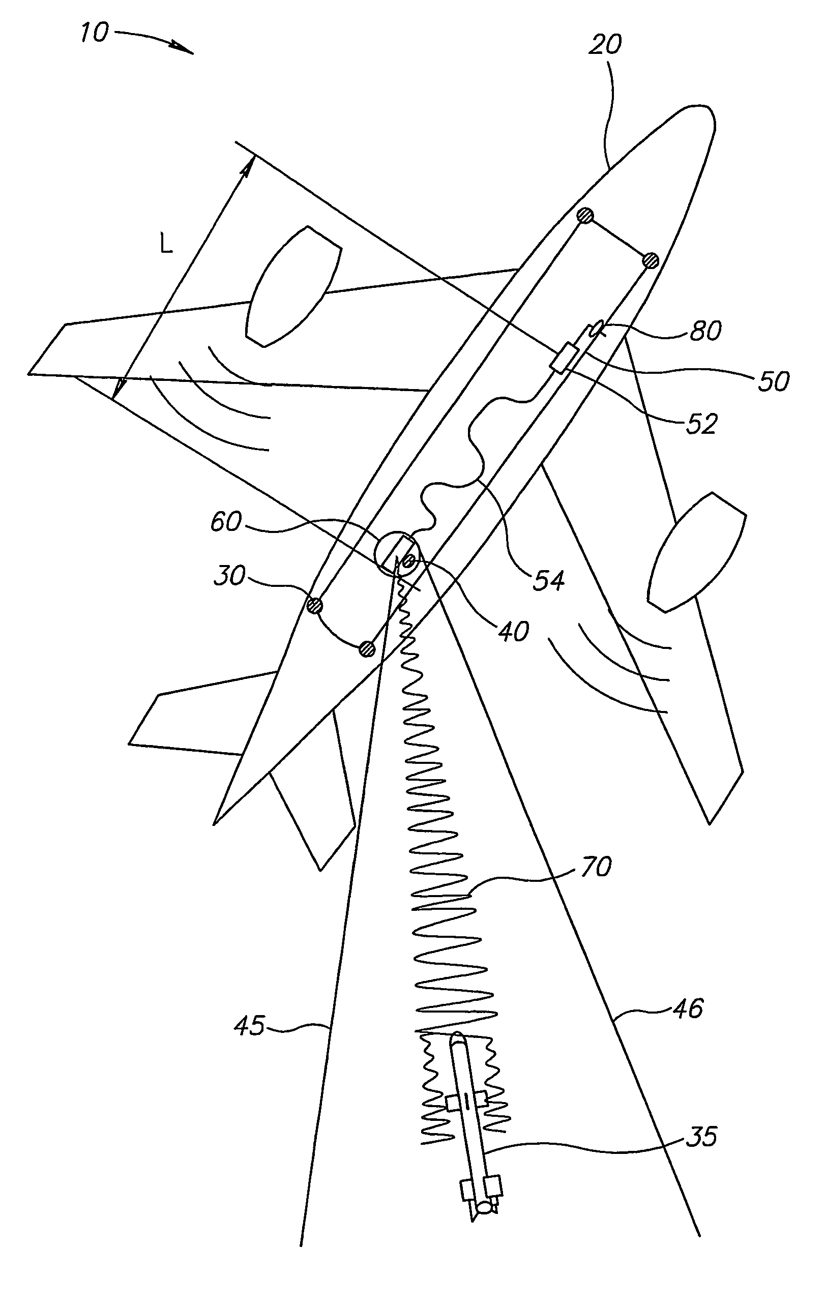
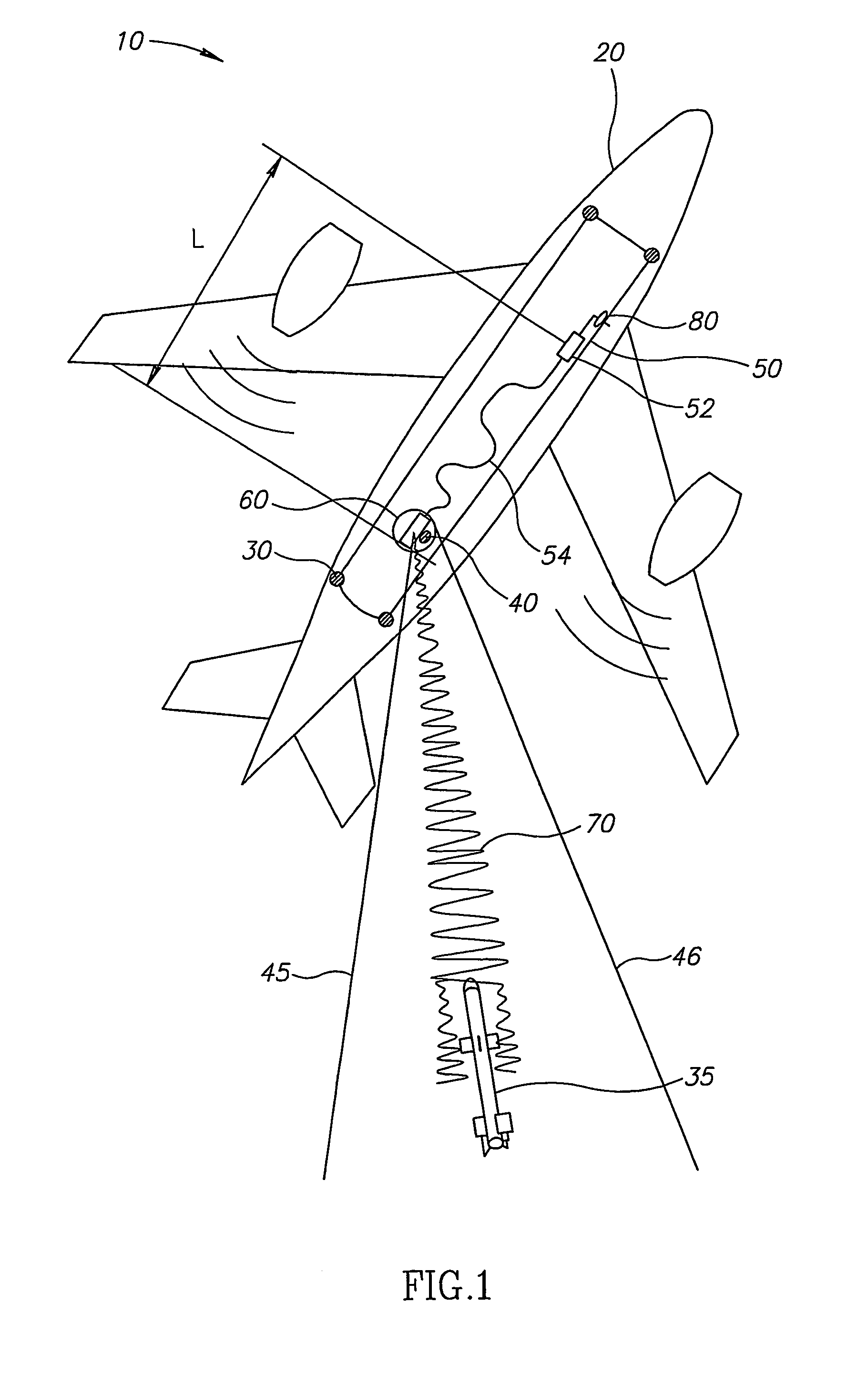
A DIRCM (Direct IR Counter Measures) system includes a detection and warning apparatus for detecting a missile that might pose a threat on the platform to which said system is allocated, and for generating a warning of its existence. The warning may include data that enable the calculation of the expected direction from which the missile is approaching. The DIRCM system may also include an acquisition device for performing acquisition of the approaching missile in accordance with the data provided by the detection and warning apparatus, and issuing data that may enable the calculation in real time of the updated position of the missile, a fiber laser for generating a laser beam, and a motion and aiming enabled turret, coupled with the laser, for directing the laser beam onto the approaching missile. The laser beam may be generated in accordance with the missile's updated position as calculated based on data received from the acquisition device, and processing means, linked to the detection and warning apparatus and also to the acquisition device, the laser and the turret.

Description

CROSS REFERENCE TO RELATED APPLICATIONS[0001]This application is a 371 filing of International Application PCT / IL2004 / 000475 filed on Jun. 3, 2004 and published in English as International Publication No. WO 2004 / 109323 on Dec. 16, 2004, and claims priority from Israeli patent application no. 156313 filed Jun. 4, 2003, Israeli patent application no. 156897 filed Jul. 13, 2003 and U.S. application No. 60 / 539,599 filed Jan. 29, 2004, all of which applications are hereby incorporated by reference herein in their entirety.FIELD OF THE INVENTION[0002]The present invention relates to the field of jamming systems that are used against thermally guided missiles, in general, and more directly to systems and methods known as Direct IR Counter Measures (DIRCM's) in particular.BACKGROUND OF THE INVENTION[0003]The continuing development of ever more lethal and sophisticated homing heads relying on reception of the heat radiation emanated by motorized moving platforms (for example, aircraft, vehi...

Claims


Application Information

Patent Timeline
Patent Type & Authority Patents(United States)
IPC IPC(8): G01S7/495H04K3/00F41G7/00G01S17/00F41H11/02F41H13/00G01S7/36G02F1/39
CPCF41H11/02F41H13/0056F42B12/382G01S7/481G01S7/495H04K3/42H04K3/45H04K3/825G02F1/39H04K2203/14H04K2203/24
Inventor ANSCHEL, ISRAELKRUPKIN, VLADIMIRLOVETT, ANDREWSACKS, ZACHARYCHOMSKI, DORONSCHIFFER, ZEEVGROSSMAN, KUTILURIA, ELENADAVID, DORONSHOSHAN, ITAMAR
Owner EL OP ELECTRO OPTICS INDS
Why Eureka
Try Eureka