
Hydrogen combustion system

a combustion system and hydrogen technology, applied in the direction of combustion types, physical/chemical process catalysts, nuclear elements, etc., can solve the problems of high cost of enlarged equipment, require additional installation and capital investment, etc., and achieve maximum treatment efficiency, small size, and simple construction

Inactive Publication Date: 2010-04-20
DE NORA PERMELEC LTD
View PDF12 Cites 7 Cited by
  • Summary
  • Abstract
  • Description
  • Claims
  • Application Information

AI Technical Summary

Benefits of technology

The present invention provides a hydrogen combustion system that is simple in construction and small in size with maximum treatment efficiency. The system uses pure state hydrogen gas without the need for premixing with air, which eliminates the need for a blower and fan. The air necessary for the reaction is supplied by drift resulting from thermal convection between the catalyst and the external. The system also minimizes the amount of hydrogen gas from the upper side of the insert pipe, ensuring uniform distribution. The catalyst is kept balanced optimally with the air flowing into the gap between the external and internal cylinders to achieve the maximum hydrogen treatment capacity. The system is designed to safely combust hydrogen gas and discharge it as safe water vapor. The position of the top of the insert pipe is at the height of 50-90% of the internal cylinder from the bottom, and a lid of non-porous metal plate may be provided at the top of the insert pipe. The diameter of the internal cylinder is determined so that the gap between the external and internal cylinders corresponds to 5-17% of the diameter of the external cylinder. The pre-heating heater is made to the same with or higher than the top of the insert pipe.

Problems solved by technology

However, these methods require additional installation and capital investment covering hydrogen gas vent piping, equipment and machinery like a blower, and introduction of discharge systems for securing safety.
As a result, a high pressure turbo-type blower is required and the volume of catalyst must be increased, which leads to a problem of high cost from enlarged equipment.

Method used


Image

  • Hydrogen combustion system
  • Hydrogen combustion system
  • Hydrogen combustion system

Examples


example 1

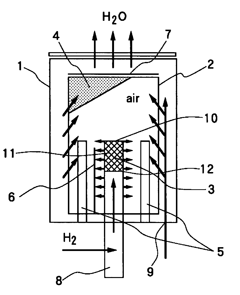
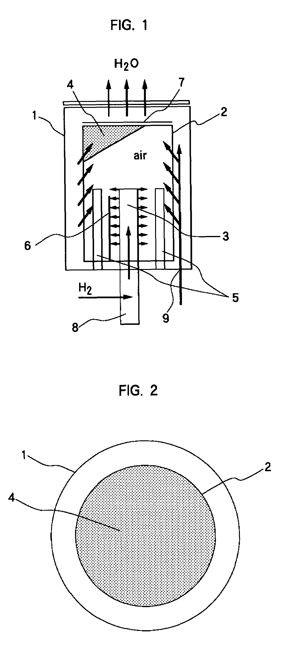
[0047]Using a system by the present invention shown in FIG. 1 and FIG. 2, about 3 liters of spherical-shape hydrogen combustion catalyst 4 with a mean spherical diameter of 6 mm supported with platinum and palladium is packed in the internal cylinder 2 with a cylindrical diameter of 100 mm and a cylindrical length of 450 mm. The pipe length and the diameter of the insert pipe are 260 mm and 45 mm, respectively. The system by the present invention was operated under the above-mentioned conditions and gave the result that when the introduced hydrogen gas flow rate was at 4.2 NL / min., the hydrogen concentration at the system exit was 0 ppm and completely combusted hydrogen gas was vented safely as water vapor.

example 2

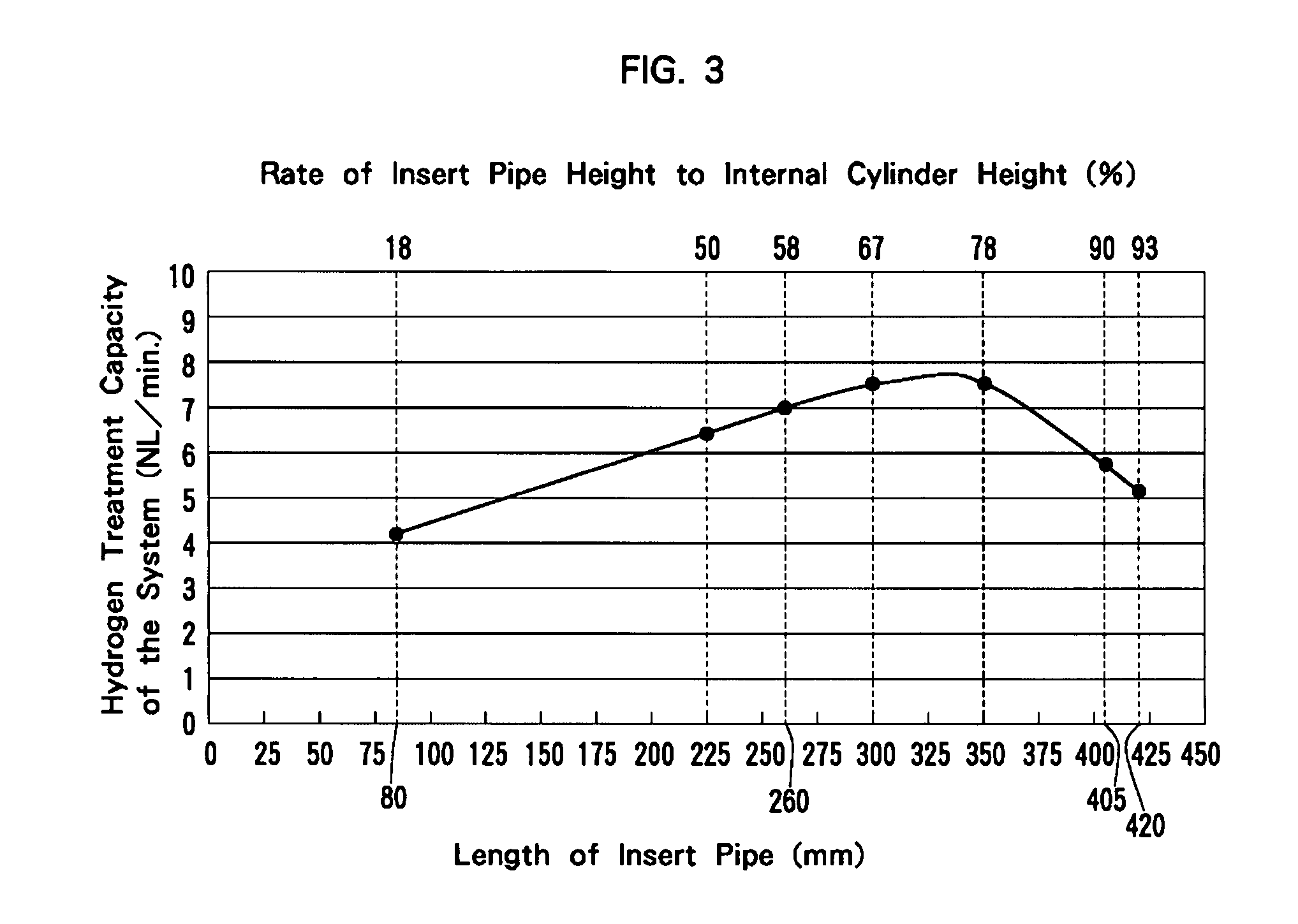
[0048]Using a system by the present invention shown in FIG. 1 and FIG. 2, about 3 liters of spherical-shape hydrogen combustion catalyst 4 with a mean spherical diameter of 6 mm supported with platinum and palladium on the ceramic support surface is packed in the internal cylinder 2 with a cylindrical diameter of 100 mm and a cylindrical length of 450 mm formed with perforated metal. At this time, the insert pipe 3 was formed with perforated metal in the same way as the internal cylinder 2. The shape of the pore of the insert pipe 3 was round and its diameter was 3 mm. The diameter of the insert pipe 3 was 45 mm and 7 kinds of the insert pipe 3 with different lengths: 80 mm, 225 mm, 260 mm, 300 mm, 350 mm, 405 mm, 420 mm were prepared. Using these 7 kinds of the insert pipe 3, the following experiments were conducted. Catalyst in the internal cylinder was heated to the predetermined temperature by the pre-heating heater 5 and then hydrogen gas by-produced in an electrolytic ozone wa...

example 3

[0053]The present invention was implemented using a system by the present invention shown in FIG. 4.

[0054]About 3 liters of spherical-shape hydrogen combustion catalyst 4 with a mean spherical diameter of 6 mm supported with platinum and palladium on the ceramic support surface is packed in the internal cylinder 2 with a cylindrical diameter of 100 mm and a cylindrical length of 450 mm formed with a perforated metal. At this time, the insert pipe 3 was formed with a perforated metal in the same way as the internal cylinder 2. The shape of the pore of the insert pipe 3 was round and its diameter was 3 mm. The diameter of the insert pipe 3 was 45 mm and the pipe length was 420 mm. Catalyst in the internal cylinder was heated to the predetermined temperature by the pre-heating heater 5 and then after preheating, hydrogen gas by-produced in an electrolytic ozone water production unit was supplied into the internal cylinder from the insert pipe 3. The height of the pre-heating heater 5 w...


PUM

PropertyMeasurementUnit
mean particle sizeaaaaaaaaaa
hydrogen combustion efficiencyaaaaaaaaaa

Abstract

A hydrogen combustion system comprising: an external cylinder 1 constituting the exterior of a double tube construction; an internal cylinder 2 formed by a porous metal plate constituting the interior of said double tube construction; hydrogen combustion catalyst 4 supported with precious metals on spherical ceramic support surface, formed in pellet state, being packed in said internal cylinder 2; an insert pipe 3 formed by porous metal plate inserted in the center of said internal cylinder 2; pre-heating heaters 5 installed between said insert pipe 3 and said internal cylinder 2 to preheat said hydrogen combustion catalyst 4 to ambient atmosphere of over catalytic reaction temperatures; a hydrogen introducing port 8 connecting to said insert pipe 3; an air introducing port 9 provided at the bottom of said external cylinder 1 in the area between said external cylinder 1 and said internal cylinder 2, wherein air for hydrogen combustion is introduced by the drift effect resulting from the differential pressure generated between the packed layer of hydrogen combustion catalyst and the outside, by thermal convection, achieving safe combustion treatment of hydrogen in simple construction, small size and high treatment efficiency.

Description

BACKGROUND OF THE INVENTION[0001]1. Field of the Invention[0002]The invention relates to a hydrogen combustion system which treats hydrogen by combustion with hydrogen combustion catalyst. More specifically, it relates to a hydrogen combustion system suitable for reacting excess hydrogen gases safely, including, though having no restriction as to kinds of feed hydrogen gases to be combusted, extra hydrogen gas generated during an operation of fuel cells, ambient atmosphere hydrogen gas at a film forming step in semi-conductor processes, electrolytically by-produced hydrogen gas from a water electrolysis system, by-product hydrogen gas from chemical reaction processes, to be discharged as water vapor from the processes.[0003]2. Description of the Related Art[0004]In general, hydrogen gases by-produced in various processes, which intrinsically involve high possibilities of explosion and leakage hazard are discharged into ambient atmosphere via exclusively provided vent pipes or via co...

Claims


Application Information

Patent Timeline
Patent Type & Authority Patents(United States)
IPC IPC(8): B01J8/02B01J8/04C01B5/00F23D14/18G21C19/30G21C9/00
CPCF23D91/02F23D14/22F23C2900/9901F23D14/18
Inventor MANABE, AKIYOSHIKATO, MASAAKIMOCHIZUKI, KAZUMASAMIMURA, MASAKAZU
Owner DE NORA PERMELEC LTD
Learn More