Shield conductor and method of producing thereof

a shielding conductor and shielding technology, applied in the direction of rigid-tube cables, power cables, cables, etc., can solve the problem that the use of shields will increase the number of parts, and achieve the effect of reducing the diameter of electric wires, superior shielding performance, and excelling heat dissipation performan

Inactive Publication Date: 2010-04-20
AUTONETWORKS TECH LTD +2
View PDF33 Cites 11 Cited by
  • Summary
  • Abstract
  • Description
  • Claims
  • Application Information

AI Technical Summary

Benefits of technology

[0010]According to this configuration, the heat generated in the electric wire is transferred to the filler, and from the filler to the pipe to be released from the outer periphery of the pipe into the atmosphere. Since the filler has a heat conductivity higher than that of air, this configuration is superior in the performance of dissipating the heat generated in the electric wire compared to a configuration without a filler.
[0011]The electric wire may be, at least over part of its length, in a form in which the outer periphery of the insulation coating is kept in contact with the inner periphery of the pipe. This configuration causes the heat generated in the electric wire to be transferred directly to the pipe without passing through the filler thereby increasing the heat dissipation efficiency.
[0012]Forming the insulation coating for the electric wire by baking a formed resin onto the surface of the conductor will reduce the electric wire diameter, thereby allowing further weight reduction.
[0013]Moreover, a structure in which multiple electric wires of a baked-on insulation coating type are placed in a pipe and are then shielded with a sheath will make it possible to effectively prevent the electric wire from coming into contact with the inner wall of the pipe when the electric wire is inserted into the pipe. Furthermore, since the electric wire is formed of an electric wire of a baked-on insulation coating type, it is possible to reduce the necessary amount of the sheath as the diameter of the electric wire decreases and therefore to achieve a weight and cost reduction of the sheath, further leading to a weight and cost reduction of the entire shield conductor.
[0017]According to the electric wire of the present invention, since the heat generated in the electric wire is effectively transferred to the pipe via the filler, the electric wire is not only superior in shielding performance, but also excels in heat dissipation performance, and therefore it is possible to reduce the diameter of the electric wire thereby achieving a weight reduction.

Problems solved by technology

For this reason, generally, a configuration in which a braided wire is enclosed with a protector made of synthetic resin is adopted; however, there is a problem that use of the protector will increase the number of parts.

Method used


Image

  • Shield conductor and method of producing thereof
  • Shield conductor and method of producing thereof
  • Shield conductor and method of producing thereof

Examples


embodiment 2

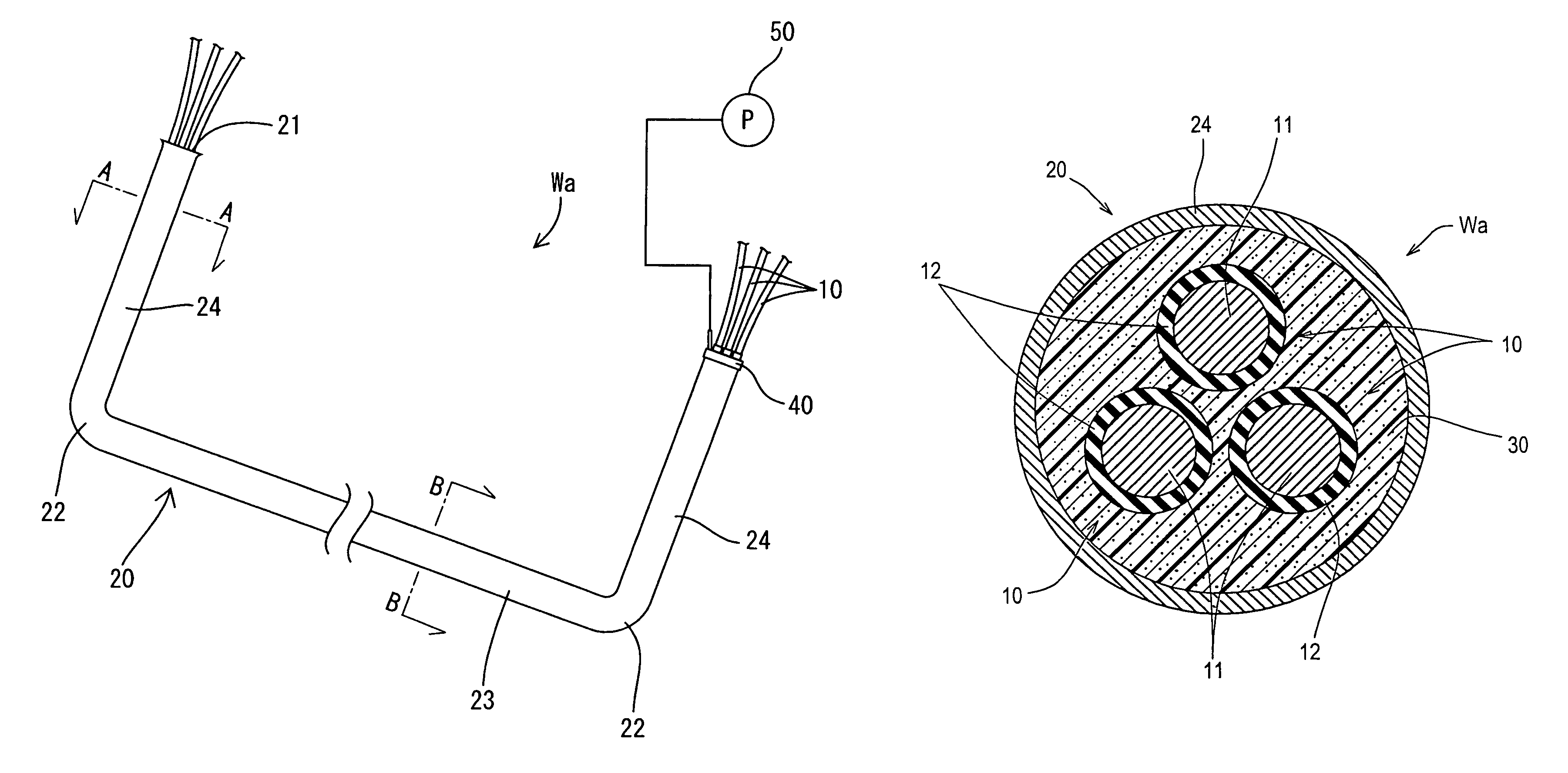
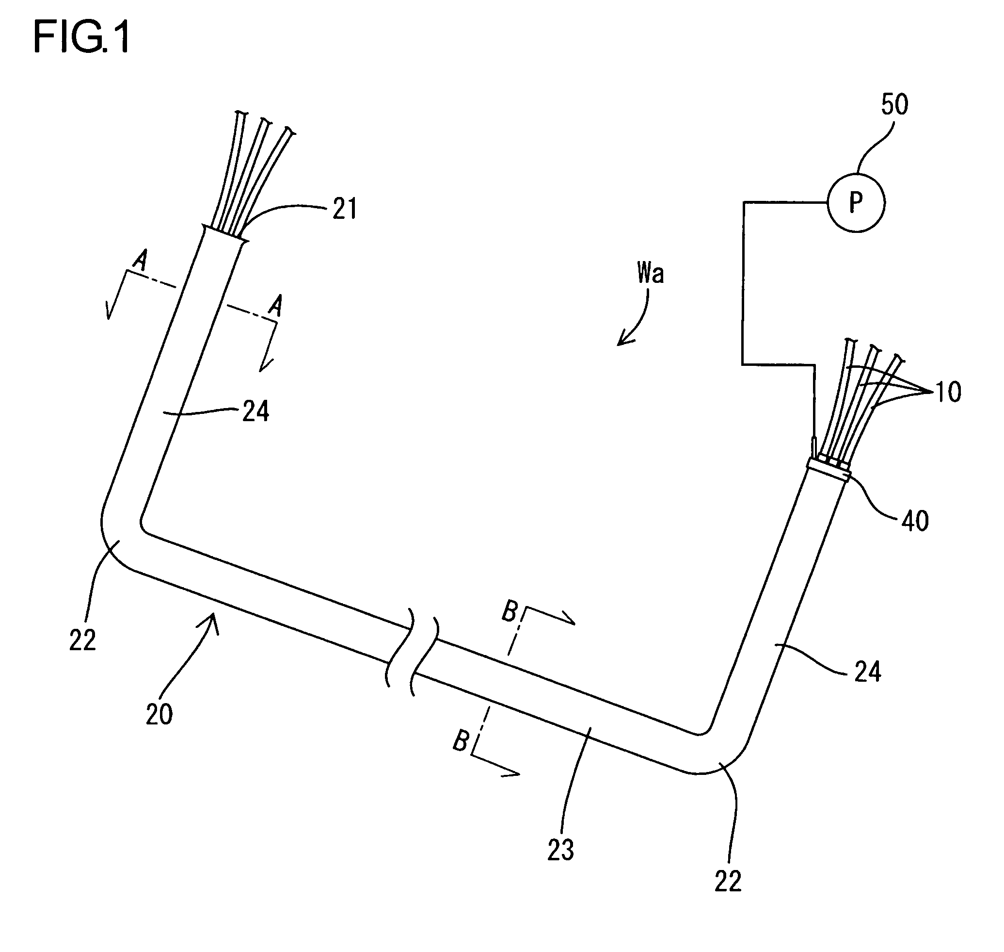
[0055]Next, the shield conductor Wc according to the embodiment 2 will be described with reference to FIGS. 9 to 14. FIG. 9 is a schematic side sectional view to exemplify the shield conductor Wc according to embodiment 2, and FIG. 10 is a sectional view taken along the line C-C of FIG. 9. The shield conductor Wc of the present embodiment, which is also wired among apparatuses (not shown) constituting, for example, a drive power source in an electric vehicle, such as a battery, an inverter, and a motor is configured such that three non-shield type electric wires 110 are inserted into a pipe 120 which combines a package shielding function and a electrical-wire protecting function.

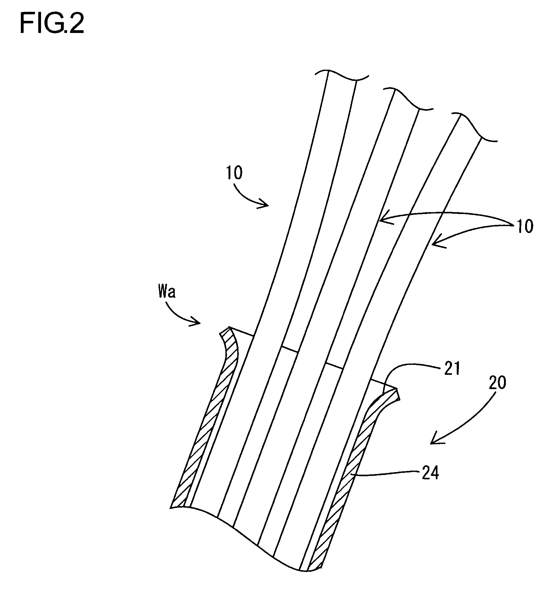
[0056]As shown in FIG. 10, the electric wire 110 is formed by baking an insulation coating 112 onto a single core conductor 111 made of a metal (such as an aluminum alloy and a copper alloy), and is configured as, for example, an enameled wire. The cross-sectional profile of the electric wire 110 is configur...


PUM

PropertyMeasurementUnit
outer diameteraaaaaaaaaa

Abstract

An improved shield connector and a method of making the same include an electric wire having a conductor with an insulation coating and a metallic pipe. The electric wire is positioned in the metallic pipe. A filler is located inside the pipe, between the electric wire and the pipe, and the filler has a heat conductivity higher than that of air.

Description

TECHNICAL FIELD[0001]The present invention relates to a shield conductor and a method of producing thereof.BACKGROUND ART[0002]For example, in an electric vehicle or a hybrid vehicle, it is necessary to use a shield conductor as power supply lines to an inverter apparatus, and from the inverter apparatus to a drive motor. As the shield conductor used in such applications, there has been considered a structure in which a plurality of non-shield electric wires are enclosed with a shield member formed of a tubular braided wire, which is formed by weaving a thin metal wire into a mesh form, to electromagnetically shield them in a package.[0003]However, in a vehicle, not only electromagnetic shielding of conductor lines, but also the protection of the electric wires (such as protection from rebounding stones during driving) needs to be considered since those shield conductors are wired on the bottom face of a vehicle body as well as in an engine room. For this reason, generally, a config...

Claims


Application Information

Patent Timeline
Patent Type & Authority Patents(United States)
IPC IPC(8): H01B7/00
CPCH01B7/16H01B7/428Y10T29/53243
Inventor WATANABE, KUNIHIKO
Owner AUTONETWORKS TECH LTD
Why Eureka
Try Eureka