
Stirling-electric hybrid automobile

a hybrid, electric technology, applied in hybrid vehicles, reciprocating combination engines, machines/engines, etc., can solve the problems of inability to generate useful amounts of power, inability to adapt inability to use such engines for automobiles, etc., to achieve slow response to varying power demands, reduce harmful emissions, and improve fuel economy

Active Publication Date: 2010-06-01
MCDOWELL JOSEPH SHEA
View PDF4 Cites 8 Cited by
  • Summary
  • Abstract
  • Description
  • Claims
  • Application Information

AI Technical Summary

Benefits of technology

"The invention is about an automobile that uses electricity to drive. The car is powered by a battery and / or capacitors that are charged by a small external combustion engine. The engine's exhaust heat is used to generate electricity using a thermoelectric generator. The car's electric motor also generates electricity during braking. The electricity can be charged from external sources. This invention improves the efficiency of the automobile and its engine."

Problems solved by technology

However use of such engines for automobiles was subsequently abandoned in favor of internal combustion engines, despite the fact that Stirling Engines pose the potential for the greatest fuel efficiency of any of the real heat engine designs, have few noxious emissions and can be run on a variety of fuels.
It appears that this abandonment resulted from the fact that Stirling Engines could not generate useful amounts of power immediately after cold start (but must be heated to operating temperature, in contrast with internal combustion engines which can generally be used immediately after starting) and the fact that Stirling Engines are not very responsive to varying power demands (accelerate and decelerate at significantly slower rate than internal combustion engines).
While significantly more “responsive” than Stirling Engines, internal combustion engines possess certain undesirable characteristics, including considerably worse fuel economy, greater emission of noxious exhaust gases (including oxides of nitrogen and carbon) and each are designed to operate on a very narrow range of fuel.
Yet the undesirable characteristics of using a Stirling Engine to drive automobiles remained to be over-come.
“All electric” vehicles, which are driven by electric motor which draws electricity from a non-board battery suffer certain disadvantages which limit their utility.
Principally these limitations relate to the limited range that may be obtained from on-board battery which is of reasonable size, weight and expense, coupled with the long time required to recharge an exhausted battery (or the impracticalities involved in changing replacing exhausted battery with a charged battery).
Hybrid-electric” vehicles which employ the use of an electric motor to drive the vehicle and an internal combustion engines (to charge the battery of the vehicle or when extra power is needed) have had some success, mainly derived from their use of a smaller internal combustion engine, shutting same down when the vehicle is at idle and use the use of regenerative braking (whereby upon braking the automobile is used as a generator to charge the battery of the vehicle), but suffer at least some degree of the disadvantages of internal combustion engines mentioned above (poor fuel efficiency, higher undesirable emissions and largely inflexible fuel requirements).
In the last two decades there appears to have some experimentation with development of a hybrid-electric vehicle that employs use of a Stirling Engine to generate electricity which charges the battery of the vehicle, delivers electric power to the automobile of the vehicle but it appears that such experimentation was unsuccessful because of a variety of problems including lower-than-expected thermal efficiency, high heat rejection requirements, poor specific power, and excessive hydrogen leakage.

Method used


Image

  • Stirling-electric hybrid automobile
  • Stirling-electric hybrid automobile

Examples


Embodiment Construction

[0017]While the present invention will be described with reference to preferred embodiments, it will be understood by those who are skilled in the art that various changes may be made and equivalents may be substituted for elements thereof without departing from the scope of the invention. In addition, many modifications may be made to adapt a particular situation or material to the teachings of the invention without departing from the essential scope thereof. It is therefore intended that the present invention not be limited to the particular embodiments disclosed as the best mode contemplated for carrying out this invention, but that the invention will include all embodiments and legal equivalents thereof which are within the scope of the appended claims.

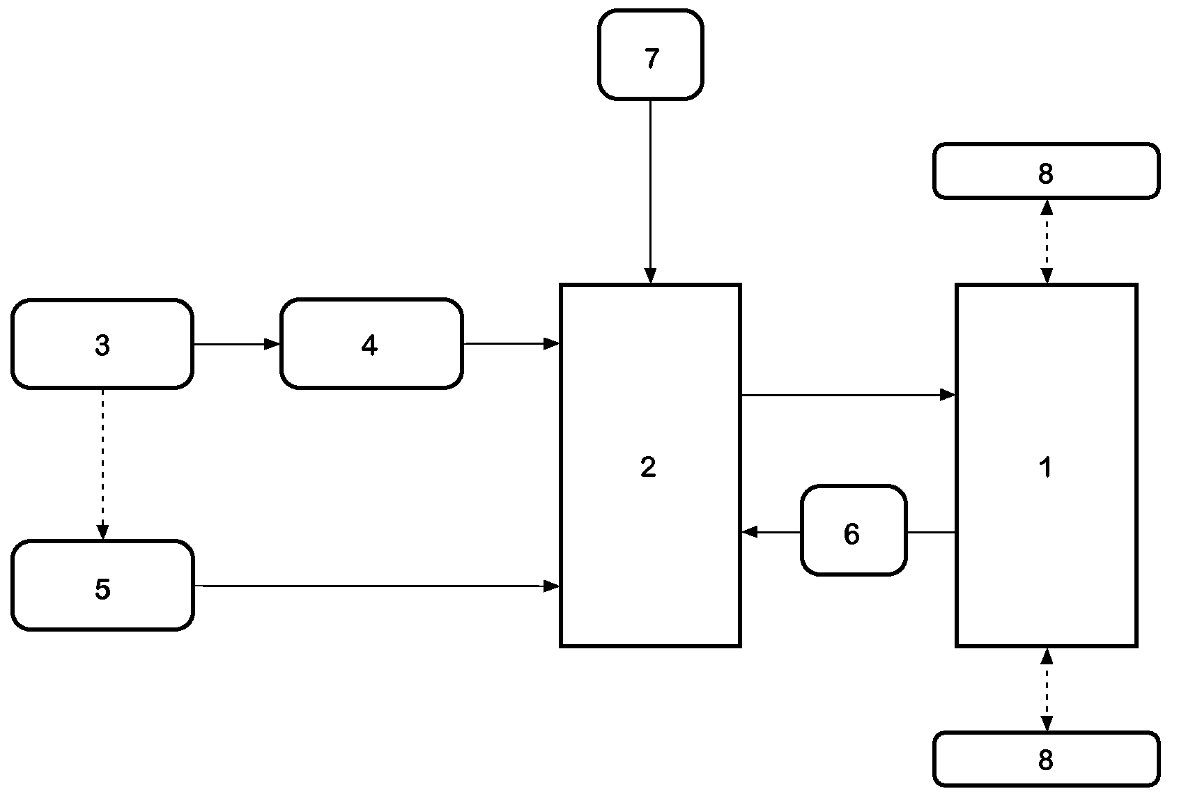
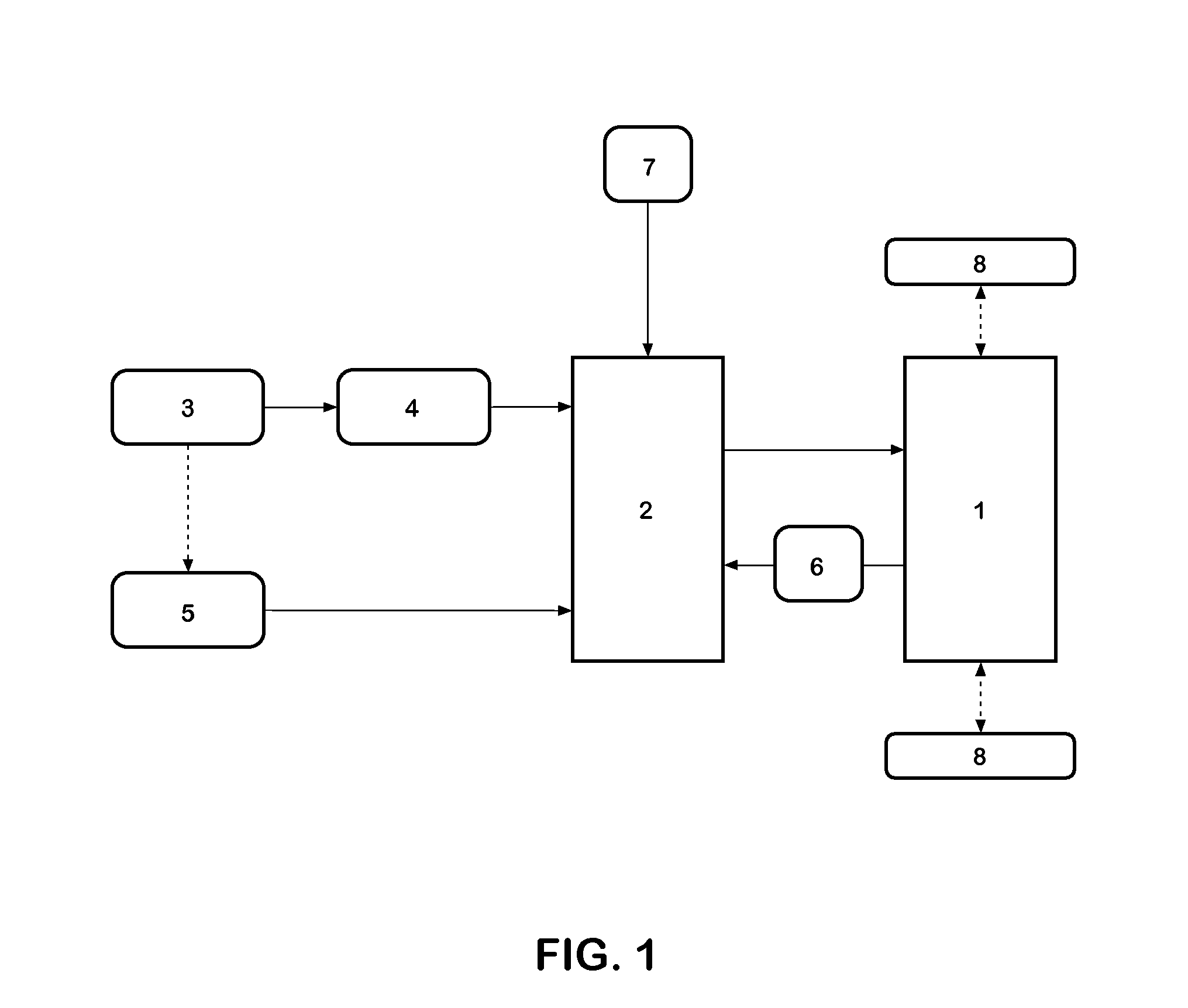
[0018]FIG. 1 is a schematic representation of the distribution of power which takes place in the Stirling-Hybrid Automobile of the invention herein disclosed and claimed. Referring to FIG. 1, automobile 1 is used to produce the mo...


PUM


Abstract

The Stirling-Electric Hybrid automobile herein disclosed utilizes an electric drive motor which is powered by electric storage device. The electric storage device is kept at suitable charge by electric generator mechanically driven by external combustion of Stirling engine type, by thermoelectric generator thermally coupled to the exhaust of the Stirling engine and to kinetic energy recovery system which during deceleration of the automobile utilizes the electric drive motor as a generator and recovering the electrical energy generated by deceleration to the electric storage device. Almost any clean combusting liquid or gaseous fuel may be utilized by the Stirling engine with greater fuel economy and less atmospheric pollution than internal combustion engines presently used. The utilization of thermoelectric generator to recover heat from exhaust of the Stirling engine and utilization of kinetic energy recovery system provides even better fuel efficiency and reduced pollution.

Description

CROSS REFERENCE TO RELATED APPLICATIONS[0001]This application relates back and claims priority to U.S. Provisional Patent Application 60 / 917,608 filed May 11, 2007.BACKGROUND OF THE INVENTION[0002]1. Field of the Invention[0003]The present invention relates generally to field of self-propelled, land vehicles primarily used for transportation of people and cargo on improved road surfaces (commonly referred to as the automotive field, but including trucks, buses and specialty vehicles). More particularly the present invention relates to what are frequently called hybrid vehicles, namely those which use two or more distinct power sources to propel the vehicle. As one of the power sources of the vehicle of the invention is electric it relates to the field of hybrid-electric vehicles. As one of the power sources of the invention is a Stirling Cycle Engine, which said engine may be operated on a wide variety of liquid fuels the invention also relates to the field of flexible fuel hybrid-e...

Claims


Application Information

Patent Timeline
Patent Type & Authority Patents(United States)
IPC IPC(8): F01B21/04
CPCB60K6/26B60K6/46Y10T477/23Y02T10/92Y02T10/6217Y02T10/62
Inventor MCDOWELL, JOSEPH SHEA
Owner MCDOWELL JOSEPH SHEA
Learn More