Catalytic reactor with swirl

a catalytic reactor and swirl technology, applied in physical/chemical process catalysts, lighting and heating apparatus, separation processes, etc., can solve the problems of smog, acid rain, depletion of stratospheric ozone, etc., to improve the combustion of catalytic fuel, promote fluid flow turbulence, and improve the current design of catalytic reactors

Inactive Publication Date: 2010-06-01
UNITED TECH CORP
View PDF10 Cites 22 Cited by
  • Summary
  • Abstract
  • Description
  • Claims
  • Application Information

AI Technical Summary

Benefits of technology

[0010]The current invention seeks to improve current catalytic reactor designs. A change in the cross-sectional area and shape of a catalytic tube or channel promotes turbulence in fluid flow passing through and around the catalytic tube. Altered turbulence levels will change the rate of heat and mass transfer and hence the effectiveness of the catalytic conversion and / or the rate of of energy exchange between the adjacent passages. By varying the area / shape along the length of the reactor the design can be tailored or optimized depending on whether the catalytic reaction or the heat exchange is to be locally enhanced or suppressed as defined by performance criteria. The cross-sectional design is used in a catalytic reactor to allow for a method of improved combustion of a catalyzed fuel by either adding to the catalyst surface area, or changing the residence time of a fluid with the catalyst, or both, and promoting mixture and swirl of the catalyzed fluid with another fluid.

Problems solved by technology

Exhaust gases produced in the combustion of hydrocarbon fuels by engines contribute to atmospheric pollution.
Nitrogen oxides are a cause of smog, acid rain, and depletion of stratospheric ozone.
Partial oxidation means that there is insufficient oxygen available to completely convert fuel to carbon dioxide and water, and thus fully liberate the chemical energy stored in the fuel.
A practical problem in the design of an integrated catalytic reactor-heat exchanger is balancing the rate of reaction and chemical heat release with the rate of heat exchanged to the adjacent cooling flow.
If not well-balanced, sections of the reactor can over heat leading to premature failures or loss of activity.
Such a strategy is generally not acceptable, however, since system performance will be adversely affected as the catalyst degrades.

Method used


Image

  • Catalytic reactor with swirl
  • Catalytic reactor with swirl
  • Catalytic reactor with swirl

Examples


Embodiment Construction

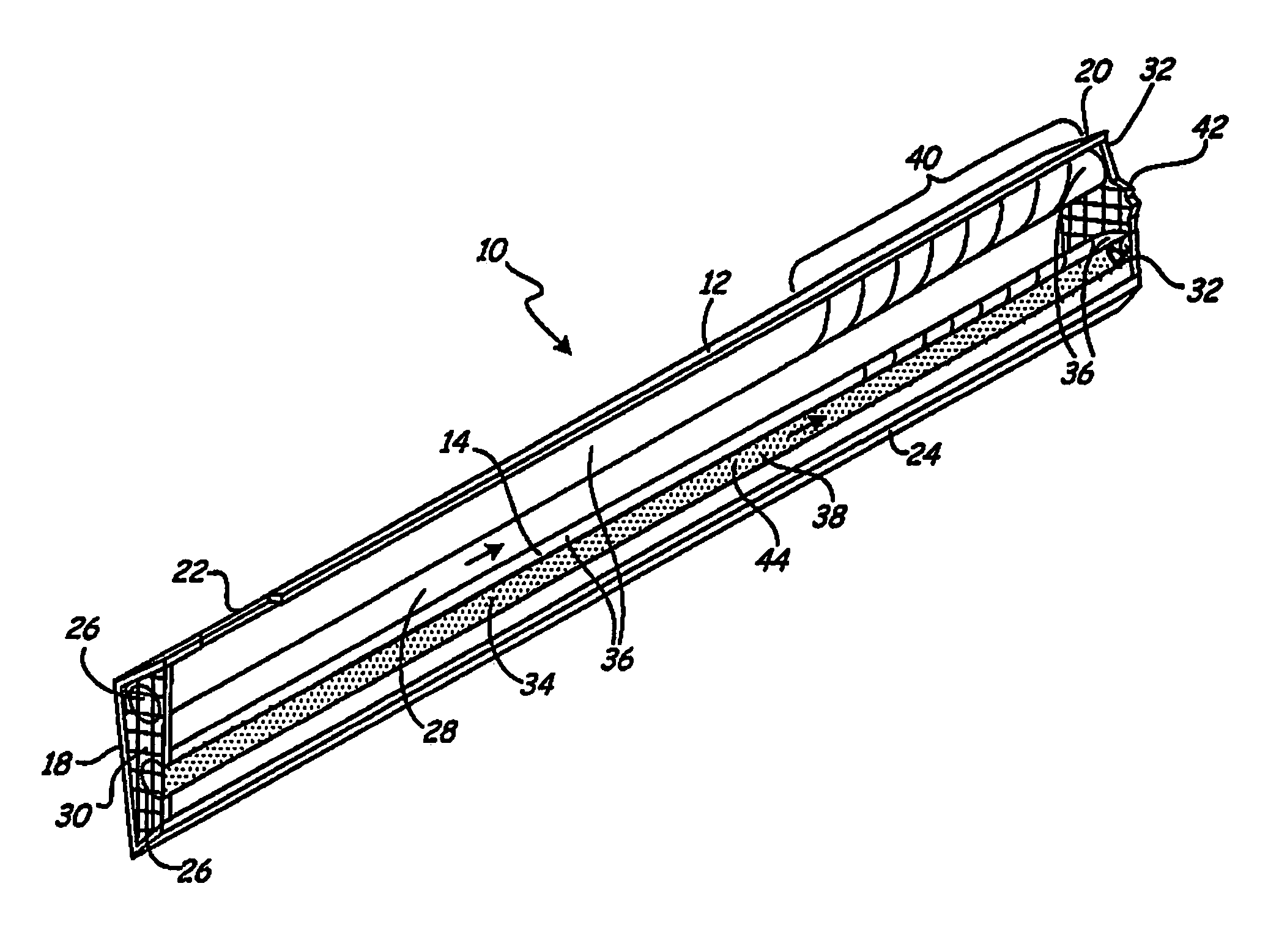
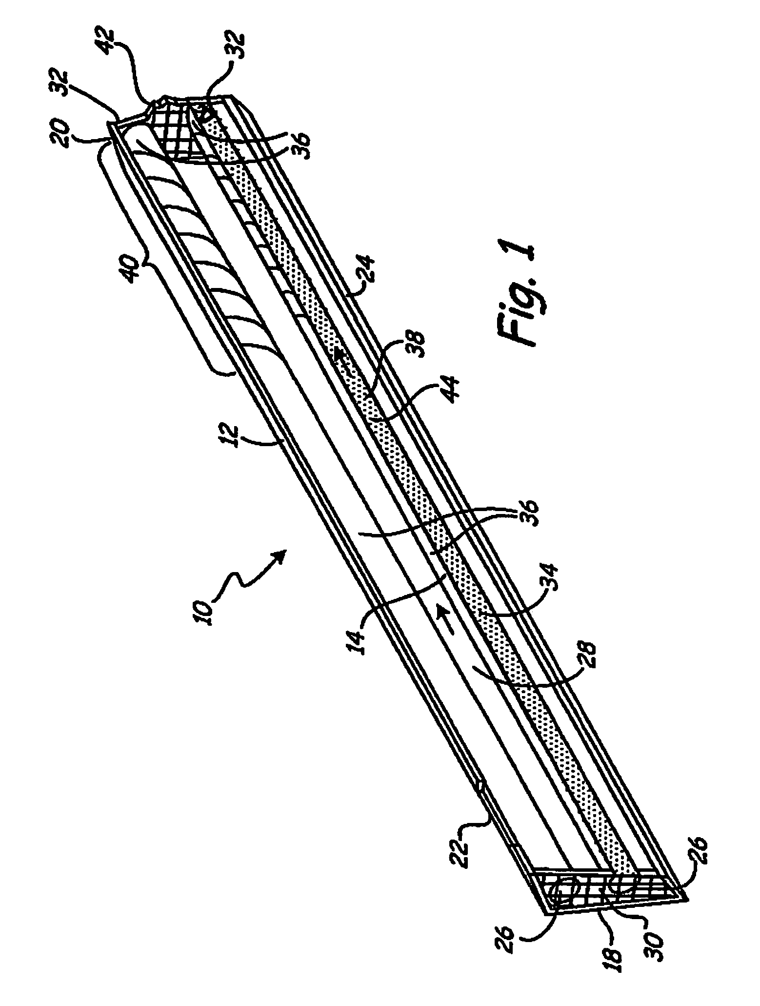
[0023]FIG. 1 depicts a longitudinal cross-section of catalytic reactor 10, which includes housing 12 and catalyst tubes 14. Catalytic reactor 10 may be integrated with a gas turbine combustion system (not illustrated). In this embodiment, housing 12 contains an entrance 18 and an exit 20. Housing 12 contains at least one aperture 22 for introducing an additional fluid into housing 12. A wall 24 of housing 12 and exterior surface 36 of catalyst tubes 14 create a fluid flow path 28 from the entrance 18 or aperture 22 to the exit 20. Entrance 18 comprises a grate 30 connected to wall 24 of housing 12. Grate 24 secures catalyst tubes 14 in place within the housing 12, while allowing for the introduction of fluids into catalyst tubes 14 and flow path 28. Grate 30 and wall 24 of housing 12 are constructed from metal or other material system suited for the application. Exit 20 allows fluids flowing within flow path 28 to exit the housing 12.

[0024]Catalyst tubes 14 are made from a heat cond...


PUM

PropertyMeasurementUnit
lengthaaaaaaaaaa
velocityaaaaaaaaaa
areaaaaaaaaaaa

Abstract

A catalyst conduit for a catalytic reactor of a turbine combustor, the conduit comprising a tube including an inlet and an outlet, and a wall with an interior surface and an exterior surface. The tube contains a variation in its cross sectional area along at least a portion of its length to change a property of a fluid flowing adjacent the wall of the tube. An oxidation catalyst is deposited on at least a portion of the tube.

Description

CROSS-REFERENCE TO RELATED APPLICATION[0001]Reference is hereby made to the following copending application, which was filed on even date with the present application: “Catalytic Reactor with Tube Inserts”, Steven W. Burd, application Ser. No. 11 / 401,021.BACKGROUND OF THE INVENTION[0002]The present invention is directed to a system and method for combusting hydrocarbon fuels in an efficient manner which minimizes pollutant emissions, particularly NOx emissions.[0003]Exhaust gases produced in the combustion of hydrocarbon fuels by engines contribute to atmospheric pollution. Exhaust gases typically contain nitric oxide (NO), nitrogen dioxide (NO2), carbon monoxide, and unburned hydrocarbons. Nitrogen oxides are a cause of smog, acid rain, and depletion of stratospheric ozone. With high combustion temperatures in an engine, oxygen and nitrogen combine to form the pollutants NO and NO2 (collectively known as “NOx”). Typical fuels reacting with air exceed the threshold temperature which...

Claims


Application Information

Patent Timeline
Patent Type & Authority Patents(United States)
IPC IPC(8): B01J8/06B01J10/00F02C1/00F02G3/00B01J35/02
CPCB01D53/9454B01J8/067B01J12/007B01J15/005F23R3/40B01J8/065Y02T10/22B01J2208/00176B01J2208/00221B01J2208/00309B01J2208/0084B01J2208/00849B01J2219/00117B01J2219/00768B01J2219/00772B01J2219/00777B01J2219/1944B01J2219/1946Y02T10/12
Inventor BURD, STEVEN W.COLKET, III, MEREDITH B.
Owner UNITED TECH CORP
Why Eureka
Try Eureka