
Method of marine electromagnetic survey using focusing electric current

a technology of electromagnetic survey and focusing current, which is applied in the field of geological studies, can solve the problems of uncontrollable spatial distribution of current density j produced by the source, inability to obtain information about this distribution in real three-dimensional heterogeneous media, and the like. resistivity methods are hardly applicable for exploration and delineation of oil and gas deposits

Inactive Publication Date: 2010-06-15
TSOY VALENTIN
View PDF7 Cites 5 Cited by
  • Summary
  • Abstract
  • Description
  • Claims
  • Application Information

AI Technical Summary

Benefits of technology

Enables the precise separation and mapping of three electro-physical parameters, enhancing the ability to explore and delineate offshore oil and gas deposits, particularly in deep water environments, by focusing the electric current and eliminating the axial component of current density, thereby improving the accuracy of hydrocarbon deposit detection.

Problems solved by technology

The reason is that the spatial distribution of the current density J produced by the source is uncontrollable, and any information about this distribution in the real three-dimensional heterogeneous media is not available.
Thus, the aforesaid resistivity methods are hardly applicable for exploration and delineation of oil and gas deposits, at least for two reasons: first, only one of the mentioned three electrophysical parameters of the surveyed medium needed for this purpose is registered; and second, the registered parameter is too rough, because it measures resistivity of the whole volume of the geological formation, in which the source's electrical field propagates.
An essential disadvantage of this method is the absence of a focusing of the electric current that excludes the horizontal components of electric current density jx or jy in the observation point.
This disadvantage does not allow solving the inverse problem by using the known solution of a mathematical physics equation for one-dimensional medium with sub-horizontal boundaries, which is needed for research of the natural heterogeneous three-dimensional media.
For this reason, the inverse problems for this approach in the 3D heterogeneous media cannot be solved correctly, and the separation of the parameters, such as the electric conductivity and the induced polarization is dubious.

Method used


Image

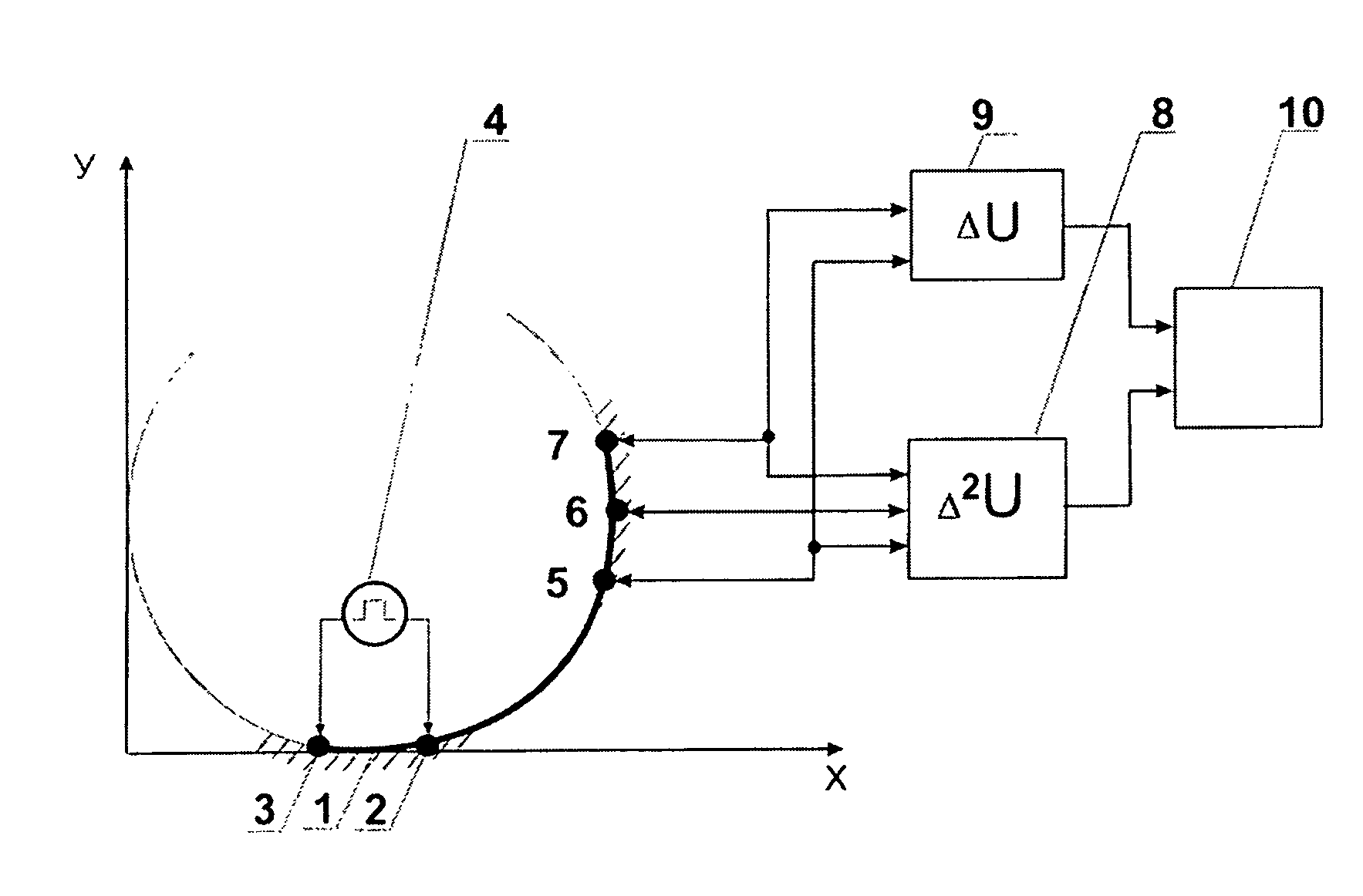
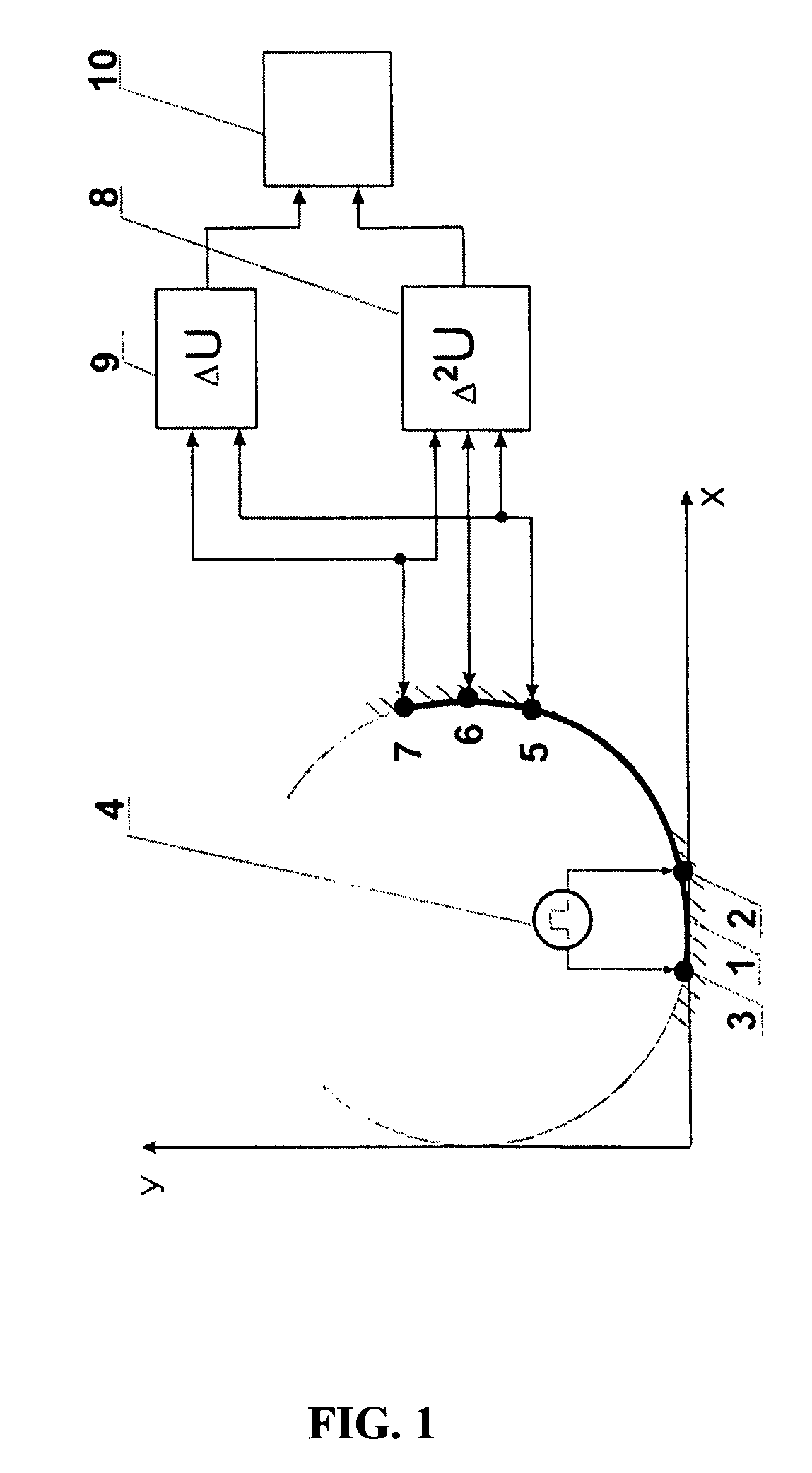
  • Method of marine electromagnetic survey using focusing electric current
  • Method of marine electromagnetic survey using focusing electric current
  • Method of marine electromagnetic survey using focusing electric current

Examples


first embodiment

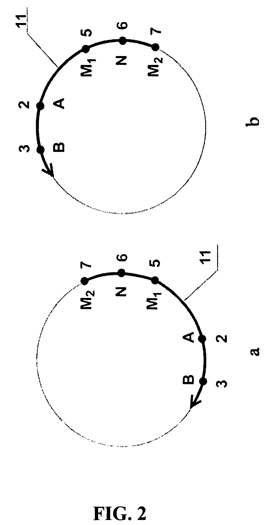
[0074]FIG. 2 shows the diagram of a circular profile line for implementation of the proposed method, using tri-electrode sensor measuring the first and the second differences of electric potentials along a circular profile line 11, at an angular distance of 90° from the dipole source AB. The measurement of the potential differences ΔUy(ti) and Δ2Uy(ti) is needed for the marine probes in deep water (50-1000 m) because these differences are absent in transient process' signals within the first isotropic non-polarizable layer (sea water) (Zhdanov, M. S., “Electric survey”, Moscow, “Nedra”, 1986, p. 259). This essentially increases the possibility to perform offshore survey and hydrocarbons exploration in deep water due to the suppression of screening influence of the highly conductive seawater layer upon the results of measurements.

second embodiment

[0075]FIG. 3 shows the block-scheme of the probe device for implementation of this method. A rectangular probe profile 12 is depicted thereon.

[0076]FIG. 4 illustrates waveforms of electric field in a homogeneous medium, wherein:[0077](a) is the waveform of current lines when using the current focusing, providing the potential difference ΔUM1M2 equal to zero; (b) is the waveform of electric field in the area of the measuring electrodes M1M2 for the current focused by using dipoles B1A1 and A2B2; (c) is the waveform of electric field in the area of the measuring electrodes M1M2 when excitation of the medium is provided by a single current dipole B1A1, without any current focusing; (d) is the waveform of electric field in the area of the measuring electrodes M1M2 when excitation of the medium is provided by a single current dipole A2B2, without any current focusing.

[0078]FIG. 5(a) illustrates a waveform of a single rectangular current pulse J of the dipole source AB, as a function of t...


PUM


Abstract

Two embodiments of marine geo-electric probe methods for hydrocarbon deposits survey comprise—excitation of electromagnetic field in a surveyed medium by transmitting two rectangular current pulses therethrough, the first—during forward traveling of a probe device along a profile and the second—during backward traveling thereof,—measuring instant values of the first and second electric potential differences during the time between the pulses, wherein, the equal-zero condition of the electric potential differences along the profile is ensured,—calculating three sets of normalized electrical parameters based on difference values,—solving an inverse problem via a differential equation for the dipole source voltage in an electrochemically polarizable medium using the parameters,—producing data according to said electrical parameters, and—determining conductivity of the medium, induced-polarization factor and decay time constant of the polarization potential difference. The first embodiment is deployed for circular survey profiles, the second is for linear profiles.

Description

CROSS-REFERENCE TO RELATED APPLICATIONS[0001]This application is a U.S. national phase application of a PCT application PCT / RU2006 / 000193 filed on 19 Apr. 2006, published as WO2006 / 130043, whose disclosure is incorporated herein in its entirety by reference, which PCT application claims priority of a Russian patent application RU2005 / 116728 filed on 1 Jun. 2005.FIELD OF THE INVENTION[0002]The invention refers to the domain of geophysical studies—specifically to methods of marine geological electromagnetic (EM) survey with the use of controllable artificial sources of electromagnetic field. It is designed for exploration and delineation of oil and gas offshore deposits of the sea shelf, and is based on the separate determination and mapping of three specific electro-physical parameters of geological formation layers: specific electric conductivity, induced polarization, and a time decay constant of the potential difference of induced polarization.BACKGROUND OF THE INVENTION[0003]Ther...

Claims


Application Information

Patent Timeline
Patent Type & Authority Patents(United States)
IPC IPC(8): G01V3/15G01V1/40G01V3/06
CPCG01V3/06G01V3/12G01V3/083
Inventor RYKHLINSKI, NIKOLAJ IVANOVICHDAVYDYCHEVA, SOFIA NIKOLAEVNALISIN, ANATOLI SEMENOVICH
Owner TSOY VALENTIN
Learn More