
Bessel analytic element system and method for collector well placement

an analytic element and collector well technology, applied in the field of analytic element system and method for collector well placement, can solve the problems of limited models and particularly difficult problems of collector wells, and achieve the effect of effective leakage calculation and easy calculation

Inactive Publication Date: 2010-08-03
LAYNE CHRISTENSEN COMPANY
View PDF3 Cites 1 Cited by
  • Summary
  • Abstract
  • Description
  • Claims
  • Application Information

AI Technical Summary

Benefits of technology

"The present invention provides an efficient and accurate model for simulating the flow of groundwater in a series of collector wells. The model takes into account the layers of the groundwater environment and the leakage between layers. It can be used in environmental science, civil and environmental engineering, water resource management, hydrology, and geology. The model is a steady-state computer code that uses Bessel analytic elements to solve the problem of groundwater flow to a partially-penetrating well in a confined aquifer. It allows for the simulation of all factors that affect the performance of the collector well, including entry resistance and frictional resistance within the collector arms. The model improves on previous collector well models by explicitly simulating the interactions between the collector well, nearby surface waters, and three-dimensional flow in porous media. It is computationally efficient and can be embedded in a large-scale regional model to account for the effects of the collector on neighboring wells and other water users. The model is the first application of Bessel analytic elements to the problem of modelling horizontal collector wells, horizontal wells, and galleries."

Problems solved by technology

Computer models of groundwater flow are commonly used in these applications, but collector wells pose a particularly challenging problem.
Many collector wells have been modelled by consultant with finite difference techniques (e.g., Sonoma County Water Agency, Louisville Water Company) but in each case the models are necessarily limited in the representation of regional flow, or in the representation of the near field conditions near the lateral arms of the collector.

Method used


Image

  • Bessel analytic element system and method for collector well placement
  • Bessel analytic element system and method for collector well placement
  • Bessel analytic element system and method for collector well placement

Examples


Embodiment Construction

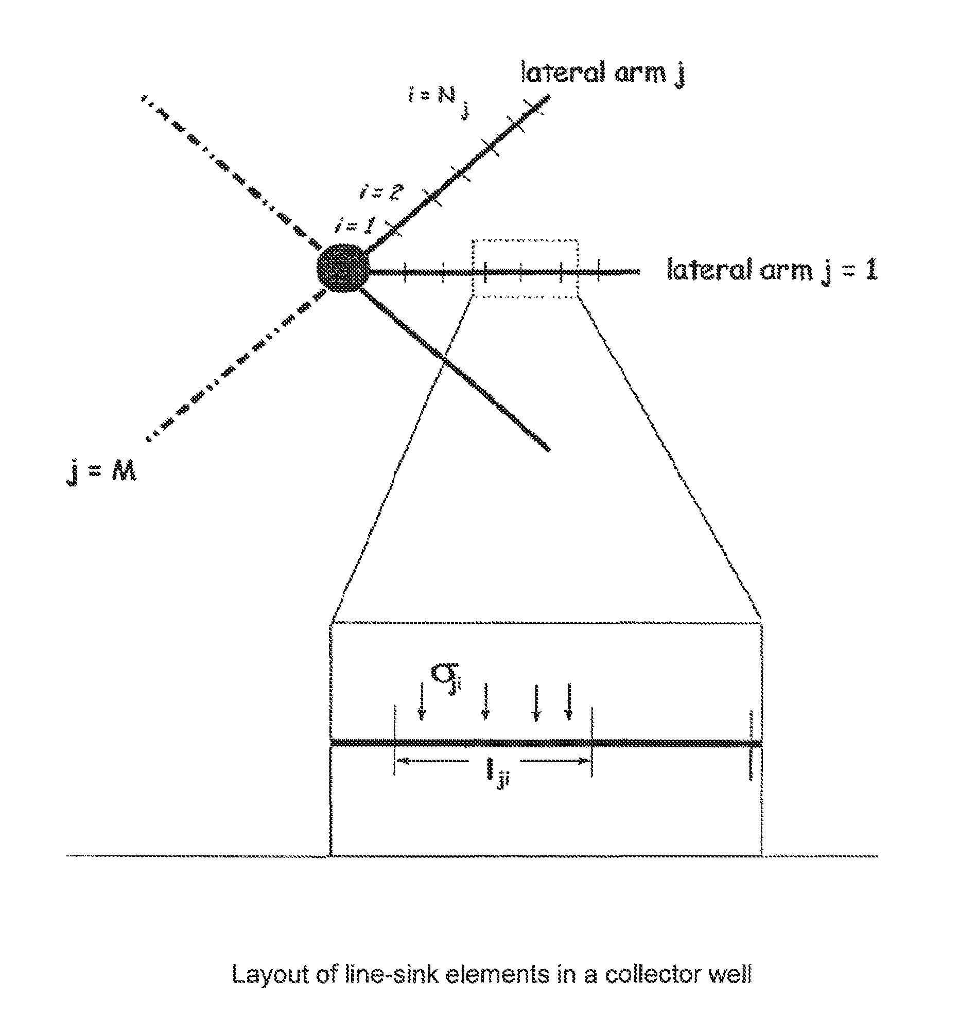
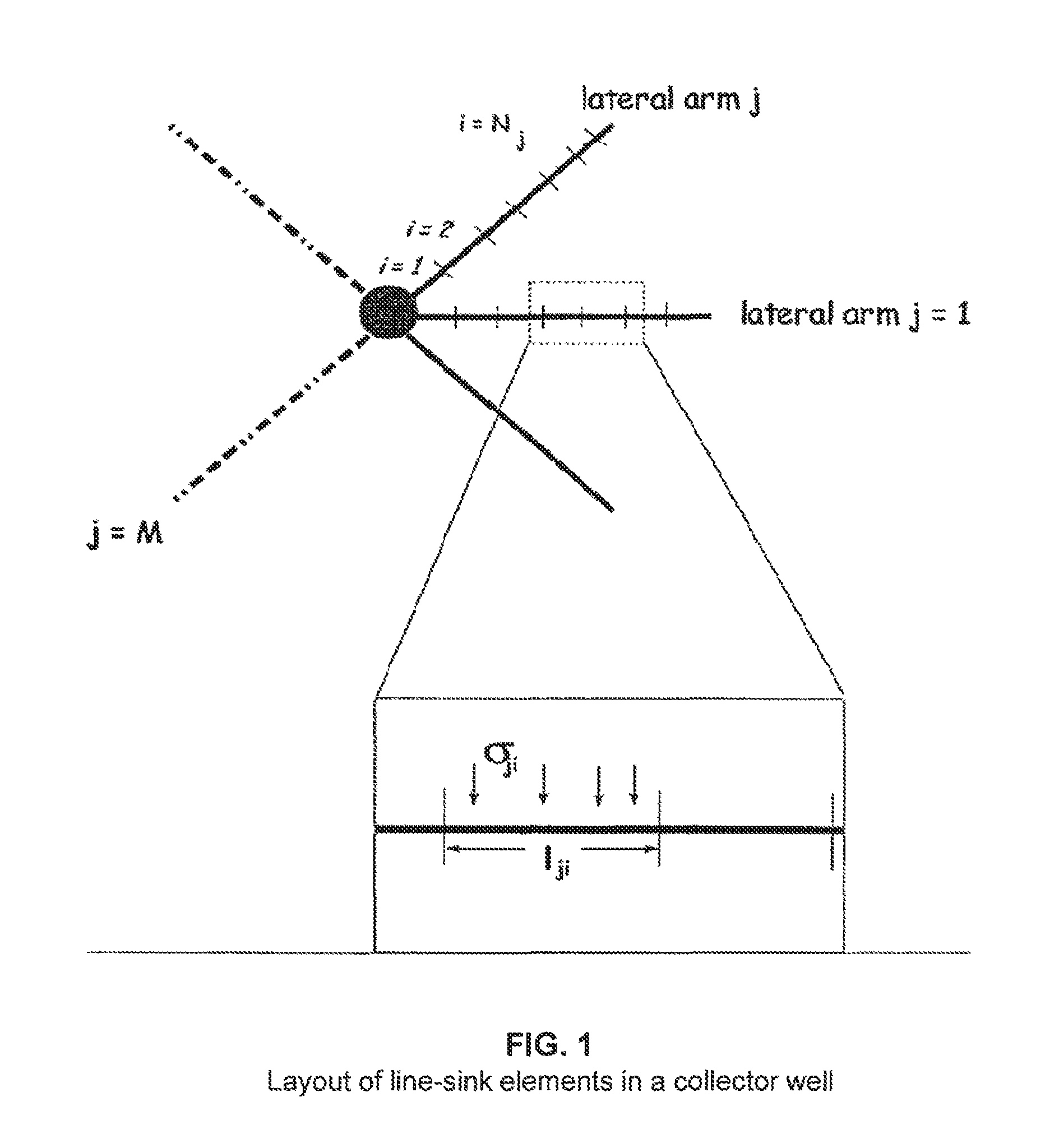
[0075]The collector well is modelled as a collection of line-sink elements as follows. Consider the collector well in FIG. 1 The collector well is composed of M lateral arms. For lateral arm j; j=1 . . . M, the arm length is Lj the radius of the arm is rj, and the lateral arm is located in model layer kj. We divide each lateral arm j into Njsegments. For segment i of lateral arm j (where i=1 at the caisson), the segment length lji is computed as

[0076]lji=Lj×Nj-i+1Sj⁢⁢where(1)Sj=∑ii=1Nj(2)

[0077]This arrangement results in shorter line-sinks at the tips of the lateral arms, and improves the accuracy of the solution. Each line-sink element has a sink density (in volume of water per day per unit length) of σji, and the head in the aquifer at all points near the collector well is a priori unknown. The modeller provides an entry resistance cji at each line-sink, which accounts for the head loss that may occur as water moves from the aquifer into the lateral arm through the well screen or ...


PUM


Abstract

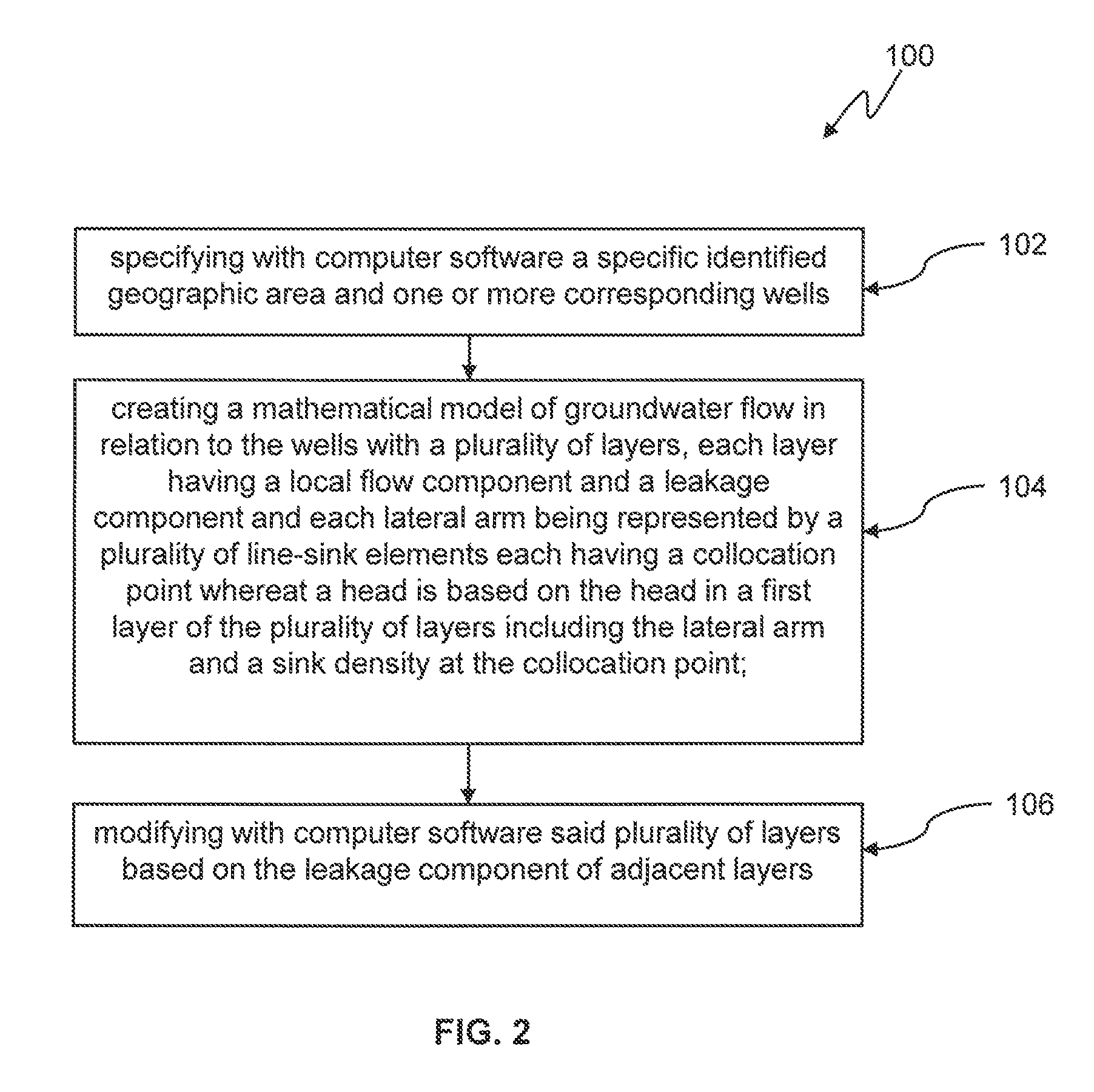
The present invention involves a method of developing a model of groundwater flow with a well configuration. First, a geographic area is specified with one or more related wells. A mathematical model is created of the groundwater flow in relation to the wells with a plurality of layers, each layer having a local flow component and a leakage component. The plurality of layers is modified based on the leakage component of adjacent layers. The simulation of groundwater flow to a collector well, horizontal well, or gallery may thus be accomplished by specifying an array of line-sink elements that represent the lateral arms of the collector well, horizontal well, or gallery. Boundary conditions for groundwater flow to the lateral arms may then be specified. Groundwater flows are then calculated based on the array and boundary conditions, with updating of the boundary conditions during the calculation. Each of the layers may include a component related to frictional head loss. The head losses due to flow into and within the lateral arms may be used to update the layers. Modifications of the models may involve calculating discharge potentials or a head specified condition.

Description

[0001]This application claims benefit of U.S. Provisional Patent Application No. 60 / 540,728 filed Jan. 30, 2004.SOURCE CODE APPENDIX[0002]This application includes a computer software specification listing appendix submitted with the aforementioned U.S. Provisional Patent Application No. 60 / 540,728 filed Jan. 30, 2004, the disclosure of which is incorporated by reference herein. A portion of the disclosure of this patent document contains material which is the subject to copyright protection. The copyright owner has no objection to the facsimile reproduction by anyone of the patent document or the patent disclosure, as it appears in the Patent and Trademark Office patent files or records, but otherwise reserves all copyright rights whatsoever.BACKGROUND OF THE INVENTION[0003]1. Field of the Invention[0004]The field of the invention is the computer modelling of steady-state groundwater flow in relation to collector wells, horizontal wells and galleries.[0005]2. Description of the Rel...

Claims


Application Information

Patent Timeline
Patent Type & Authority Patents(United States)
IPC IPC(8): G06F17/10G06G7/48E03B1/00
CPCE03B1/00
Inventor KELSON, VICTOR ABAKKER, MARKWITTMAN, JOHN F
Owner LAYNE CHRISTENSEN COMPANY
Learn More