Method of etching structures into an etching body using a plasma

a technology of etching structure and plasma, which is applied in the direction of fluid pressure measurement, instruments, coatings, etc., can solve the problems of limiting the efficacy of substrate bias pulse pause, discharging structure, and driving the pause time required, so as to eliminate the attack on the side walls

Inactive Publication Date: 2010-08-31
ROBERT BOSCH GMBH
View PDF54 Cites 12 Cited by
  • Summary
  • Abstract
  • Description
  • Claims
  • Application Information

AI Technical Summary

Benefits of technology

[0007]The object of the present invention is to provide additional variants of the method and / or exemplary embodiments for etching structures into an etching body based on the un-published German Patent Application No. 101 45 297, such that these variants result in improved pocket stability, in particular at high aspect ratios of the etched structures, and thus allow high overetching times with these structures as well.
[0011]It is also advantageous that the method according to the present invention, regardless of specific etching methods, is suitable for a number of applications, e.g., etching dielectric layers, opening of etching base passivation without damage to side wall passivation or use in etching operations based on chlorine or bromine chemistry while eliminating attack on side walls and undercutting beneath the edge of the mask. In particular, in addition to use in a silicon etching method according to German Patent No. 42 41 045 and its further embodiments, this method may also be used in structuring silicon dioxide or other dielectrics, contact hole etching and / or creating vias in SiO2 or other dielectrics and Teflon passivation of side walls of structures.

Problems solved by technology

Thus, even with the acceleration voltage turned off, only directed ions and undirected electrons are able to reach the substrate, which limits the efficacy of substrate bias pulse pauses according to German Published Patent Application No. 199 57 169 for discharging structures, i.e., it drives the pause times required for discharge into unfeasible ranges.

Method used


Image

  • Method of etching structures into an etching body using a plasma
  • Method of etching structures into an etching body using a plasma
  • Method of etching structures into an etching body using a plasma

Examples


Embodiment Construction

[0024]To implement the exemplary embodiments explained below, the plasma etching system as described in German Patent Application No. 101 45 297 shall be assumed here. In particular, the reference numbers used there are also used here with the same meanings, so they need not be explained again here.

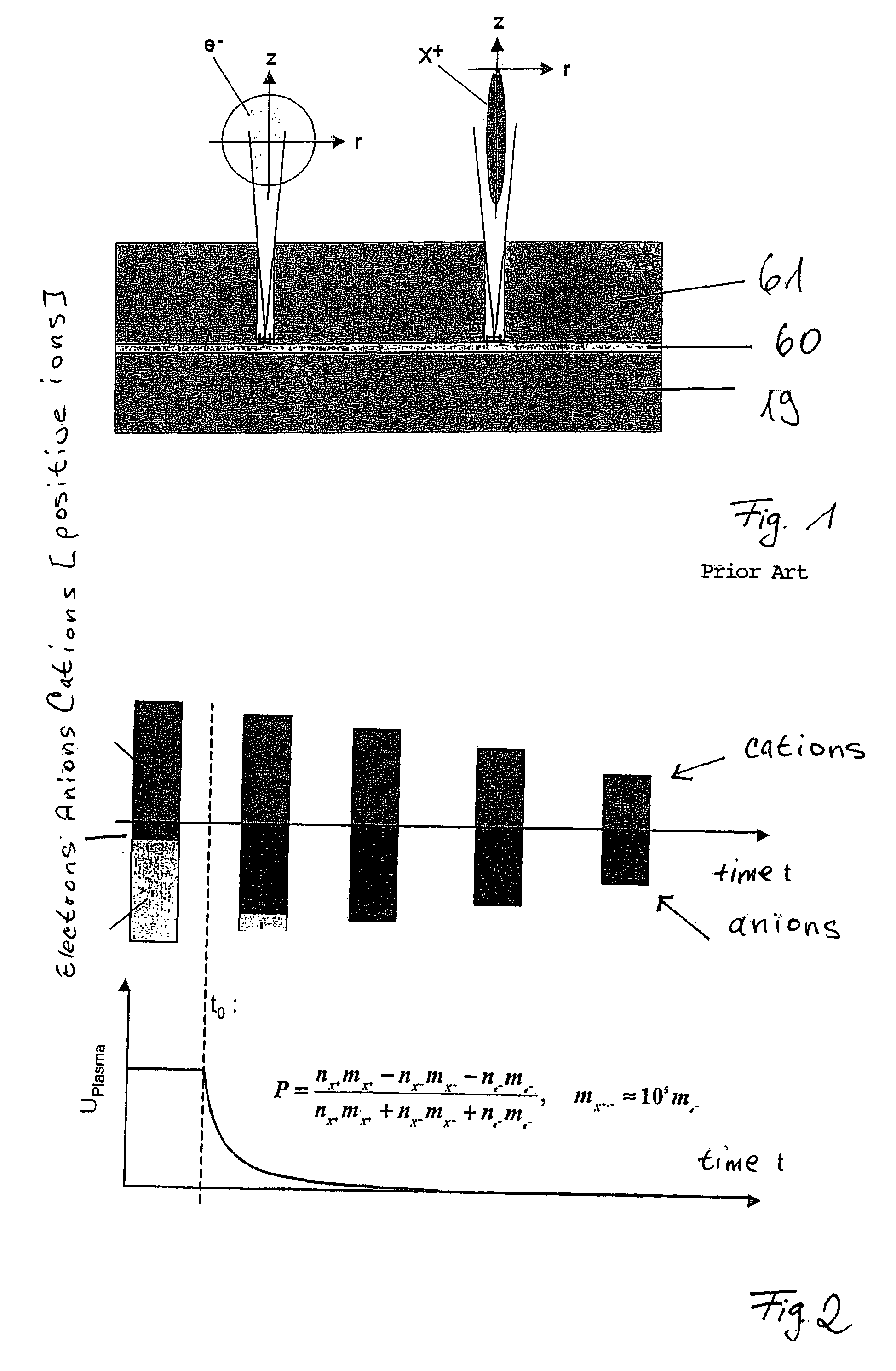
[0025]FIG. 2 shows the effects which occur in the pulse pause when a plasma is turned off, in particular when a pulsed plasma is turned off. First, starting from a “normal plasma” composed of a low density of anions and a high density of electrons and cations during the pulse period, the plasma is temporarily turned off at time t0. In the pulse pause which then begins, the electron gas in the plasma cools down within a few microseconds, resulting in recombination of electrons with cations to some extent and a paired loss of both species, but on the other hand, a substantial portion of the electrons is also captured by neutral gas molecules, forming anions. This effect is supported by a dr...


PUM

PropertyMeasurementUnit
frequencyaaaaaaaaaa
frequencyaaaaaaaaaa
thicknessesaaaaaaaaaa

Abstract

Additional variants of the method of etching structures into an etching body, in particular recesses in a silicon body that are laterally defined in a precise manner by an etching mask, using a plasma, is described. In addition, the use of this method in the introduction of structures, in particular trenches having a high aspect ratio, into a dielectric layer or a dielectric base body and in a layer of silicon is described, isotropic underetching and / or isotropic, sacrificial-layer etching, in particular using fluorine radicals or a highly oxidizing fluorine compound such as ClF3, being performed after the production of the structures in at least some areas in the case of the layer made of silicon.

Description

FIELD OF THE INVENTION[0001]The present invention relates to a method of etching structures into an etching body, in particular recesses in a silicon body that are laterally defined in a precise manner, using a plasma.BACKGROUND INFORMATION[0002]In plasma etching, a known problem resulting from electric charge buildup is the development of pockets on a dielectric interface which functions as an etch barrier. This “notching phenomenon” limits the aspect ratios of trenches such as those needed for micromechanical structures, because the overetching times allowed without the development of “notches” or “pockets” become progressively shorter as the aspect ratio (ratio of depth to width) increases. Therefore, for a process that is reliable in production, values of approx. 5:1 to 10:1 are currently thought to be the aspect ratio limit, depending on the geometry of the structure, so that yaw rate sensors, for example, are implemented not by using optimum layer thicknesses of more than 20 μ...

Claims


Application Information

Patent Timeline
Patent Type & Authority Patents(United States)
IPC IPC(8): G01L21/30B44C1/22C23F1/00C23C4/00H01J37/32H01L21/3065
CPCB81C1/00579H01J37/32082H01J37/32155H01L21/3065H01J2237/3347
Inventor URBAN, ANDREALAERMER, FRANZBREITSCHWERDT, KLAUSBECKER, VOLKER
Owner ROBERT BOSCH GMBH
Why Eureka
Try Eureka