
Rotary clock synchronous fabric

a synchronous fabric and clock technology, applied in the field of circuit design and layout, can solve the problems of loss of information that associates the parent module, poor run-time of tool, and much worse than linear run-tim

Inactive Publication Date: 2010-09-28
ANALOG DEVICES INC
View PDF20 Cites 47 Cited by
  • Summary
  • Abstract
  • Description
  • Claims
  • Application Information

AI Technical Summary

Benefits of technology

This approach enhances timing closure, reduces wire length, and optimizes placement and routing, thereby improving the efficiency and speed of integrated circuit design while minimizing timing violations and power consumption.

Problems solved by technology

First, the hierarchy is expanded resulting in the loss of information that associates the parent module for a particular cell or sub-module.
Second, tool run-times become much slower.
Run time is much worse than linear with problem size.
Flat placement runs can take days to complete and performing static timing analysis can also be very time consuming.
Recently, with DSM effects (Deep Submicron Effects, interconnects and placements (physical effects)) dominating the design challenge, the partitioning and clustering implicit in the Logical Hierarchy chosen by a designer, who is likely unfamiliar with these effects, is unlikely to be optimal.
Conversion from high-level source code into low-level netlists increases designer productivity but prevents performance-boosting ‘handcrafted’ optimizations that are possible in a non-automated custom flow.
The first automated logic synthesis tools did not factor physical effects such as interconnect capacitance, wire length, crosstalk into the logic synthesis process and did the mapping of logic-function to cells based solely on area or speed of the cells themselves, producing poor results.

Method used


Image

  • Rotary clock synchronous fabric
  • Rotary clock synchronous fabric
  • Rotary clock synchronous fabric

Examples


Embodiment Construction

[0043]In one embodiment of the present invention, an existing chip is retrofit with a rotary clock. This helps to close timing, hardly affects placement, requires a few wiring changes. A snake router is used.

[0044]The starting point for Rotary Clock retrofit is a finished physical chip design, created using standard tools and CTS (clock tree synthesis tool). This chip typically has been synthesized, designed and timed based on the assumption of single-phase clocking scheme with edge-triggered DFF storage elements. The design need not meet timing (Static Timing Analysis) as designed as the insertion of Rotary Clock can solve many of the timing violations.

[0045]In this embodiment, the existing chip design is first loaded into the database. Approximately 0% to 5% of distributed “whitespace” on the active area should exist in the standard cell areas of the design to allow for insertion of Rotary Clock cells. Sometimes the required area can be gained just through removal of existing cloc...


PUM


Abstract

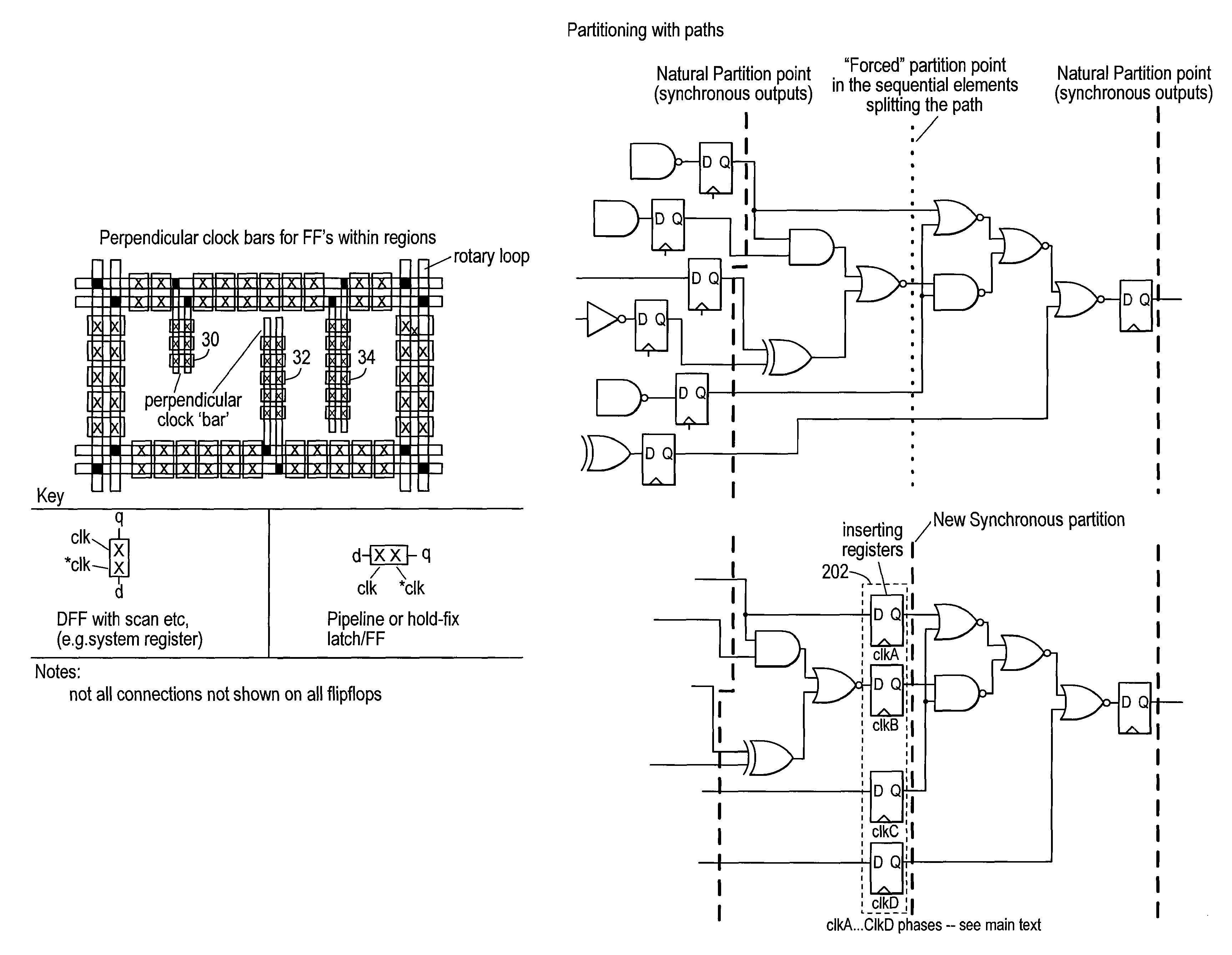
Methods for generating a design for logic circuitry using rotary traveling wave oscillators (RTWOs) are described. A plurality of RTWOs are is arranged into an array of rows and columns. Adjacent elements in the array are interconnected so that the clocks in adjacent element are phase synchronous. Clocked devices are placed along the signal path of each array element and each is connected to one of the multiple phases provided by the RTWO element. The logic circuitry, described by a netlist, is divided into a number of partitions and each of these partitions is mapped to one of the array elements. The logic circuitry of the partition is then placed within or about the element of the array to which the partition is mapped and the circuitry in the partition is connected between the clocked devices in the element of the array, according to the net list.

Description

CROSS-REFERENCE TO RELATED APPLICATIONS[0001]This application is a continuation-in-part of U.S. Application, U.S. Application, titled “Timing Circuit CAD”, Ser. No. 10 / 497,730, now U.S. Pat. No. 7,203,914, published as US2005 / 0010883, which application is a national stage application for international application PCT / GB02 / 05514, filed Dec. 6, 2002.[0002]This application is related to and incorporates by reference the following applications:[0003]GB0203605.1, titled “Hierarchical Clocking System”, filed in Great Britain on Feb. 15, 2002, now included in U.S. application titled “Electronic Circuits”, Ser. No. 10 / 504,559;[0004]GB0212869.2, titled “Rotary Clock Design Flow”, filed in Great Britain on Jun. 6, 2002, now included in U.S. application, titled “Electronic Circuits”, Ser. No. 10 / 504,559;[0005]GB0129352.1, titled “Timing Etc Circuitry”, filed in Great Britain on Dec. 7, 2001, now included in U.S. application, titled “Timing Circuit CAD”, Ser. No. 10 / 497,730; and[0006]PCT / GB03 / 0...

Claims


Application Information

Patent Timeline
Patent Type & Authority Patents(United States)
IPC IPC(8): G06F17/50
CPCG06F17/5036G06F17/505G06F17/5072G06F30/367G06F30/327G06F30/392H03B5/1852
Inventor WOOD, JOHN
Owner ANALOG DEVICES INC
Learn More