Interchangeable bearing blocks for drill bits, and drill bits including same

a technology of bearing blocks and drill bits, which is applied in the direction of drilling rods, drilling pipes, cutting machines, etc., can solve the problems of pdc cutters still suffering from what might simply be termed “overloading, excessive bit aggressiveness, and the like, and achieves the reduction of the required inventory count of bits, the reduction of manufacturing tolerance uncertainty, and the reduction of the complexity of obtaining a tdoc

Active Publication Date: 2010-10-19
BAKER HUGHES HLDG LLC
View PDF30 Cites 44 Cited by
  • Summary
  • Abstract
  • Description
  • Claims
  • Application Information

AI Technical Summary

Benefits of technology

[0014]In accordance with a first embodiment of the invention, an interchangeable bearing block comprising at least an abrasion- and erosion-resistant rubbing surface for use with a PDC drill bit. The block may be configured to provide a specified TDOC upon a bit body, which may also be characterized as a bit “frame,” in order to minimize manufacturing tolerance uncertainty and reduce the complexity in obtaining a TDOC otherwise associated with conventional drill bit fabrication techniques. Also, the block enables selection of a bearing or rubbing surface area without necessitating alteration to the bit frame of a drill bit. Moreover, the block allows for different TDOCs and / or rubbing surface areas to be selectively chosen for a given bit frame to accommodate formations exhibiting a substantial variance in compressive strengths, reducing required inventory count for bits and further facilitating re-fabrication in order to provide a different TDOC and / or rubbing surface area on a given bit. Further, the block increases precision of cutter exposure and rubbing area by eliminating manufacturing sensitivities associated with the use of hardfacing to provide a controlled cutter exposure. Furthermore, the block may include or be surfaced with abrasion-resistant materials to enhance the life of the bit. In addition, by providing a block having modifiable attributes that is selectively attachable to a given bit frame, reparability of a bit frame improves and inventory flexibility increases by enabling improved design rationalization without necessitating modification to a bit frame configuration.
[0015]In another embodiment of the invention, a cutter block is provided that includes a precise, wear-resistant bearing or rubbing area, the block being interchangeably attachable to a standardized bit or bit frame. The block provides a bearing or rubbing area specifically tailored to withstand axial or longitudinal WOB loading of the bit, by supporting, without exceeding, the compressive strength of a selected formation being drilled.
[0016]A further embodiment of the invention includes a bearing block having a precision TDOC, which may be characterized as the distance between the outermost (cutting) edges of the PDC cutters associated with the block and the rubbing surface of the block. Resultantly, the cutter block, when inserted into a receptacle on the face of a drill bit body or frame, defines the TDOC for the plurality of associated cutters. Accordingly, providing a discrete, separately fabricated block offering a precise TDOC and / or bearing rubbing area, allows the block to be fabricated without modification of the bit body.
[0018]Accordingly, a bearing block is provided that may be used with one or more blades of a bit body or frame. The block is designed so that it may be replaced or repaired, typically, without necessitating alteration to a standardized bit frame. The interchangeable block may offer a precise TDOC and / or a bearing or rubbing area for improving drilling performance of a bit. The block may or may not carry cutters; in the latter instance, the receptacle for the block on the bit body is placed in close proximity to those cutters for which DOC is to be controlled by that block, The block may be located substantially in the cone region on a blade of the bit frame, or may also be located in a region bridging the cone and the nose or, optionally, in the nose region. The interchangeable block brings manufacturing selectability by providing a product customizable for use in a variety of subterranean formations and suitable for use with a common bit frame, thus, not requiring a complex assortment of stocked bit frames. Blocks providing different TDOCs and different bearing areas may be selected as desired for insertion into a bit frame, allowing a bit to be customized or adapted for different drilling applications, including different formations, and for use with different drilling systems in terms of power, hydraulic flow and drilling fluids. A single bearing block may provide different TDOCs and more than one bearing or rubbing areas, of different surface areas.

Problems solved by technology

Even in view of such improvements, however, PDC cutters still suffer from what might simply be termed “overloading” even at low weight-on-bit (WOB) applied to the drill string to which the bit carrying such cutters is mounted, especially if aggressive cutting structures are employed.
The problem of excessive bit aggressiveness is particularly significant in low compressive strength formations where an unduly great depth of cut (DOC) may be achieved at extremely low WOB.
The problem may also be aggravated by drill string bounce, wherein the elasticity of the drill string may cause erratic application of WOB to the drill bit, with consequent overloading.
Moreover, operating PDC cutters at an excessively high DOC may generate more formation cuttings than can be consistently cleared from the bit face and back up the bore hole via the junk slots on the face of the bit by even the aforementioned improved, state-of-the-art bit hydraulics, leading to the aforementioned bit balling phenomenon.
Another, separate problem involves drilling from a zone or stratum of higher formation compressive strength to a “softer” zone of lower compressive strength.
The abruptly higher torque, in turn, may cause damage to the cutters and / or the bit body itself.
In directional drilling, such a change causes the tool face orientation of the directional (measuring-while-drilling, or MWD, or a steering tool) assembly to fluctuate, making it more difficult for the directional driller to follow the planned directional path for the bit.
In addition, a downhole motor, such as drilling fluid-driven Moineau-type motors commonly employed in directional drilling operations in combination with a steerable bottomhole assembly, may completely stall under a sudden torque increase.
Such interruptions in the drilling of a well can be time consuming and quite costly.
While some of the foregoing patents recognize the desirability to limit cutter penetration, or DOC, or otherwise limit forces applied to a borehole surface, the disclosed approaches are somewhat generalized in nature and fail to accommodate or implement an engineered approach to achieving a target ROP in combination with more stable, predictable bit performance.
Furthermore, the disclosed approaches do not provide a bit or method of drilling which is generally tolerant to being axially loaded with an amount of weight-on-bit over and in excess what would be optimum for the current rate-of-penetration for the particular formation being drilled and which would not generate high amounts of potentially bit-stopping or bit-damaging torque-on-bit should the bit nonetheless be subjected to such excessive amounts of weight-on-bit.
Moreover, the foregoing patents do not provide a bit wherein the TDOC and the designed bearing (which may also be termed “rubbing”) surface area, i.e., potential contact area with the “to be” drilled subterranean formation, are simultaneously provided for in a structure selectively attachable to a given bit frame, in order to provide variety and selectability of the TDOC and the designed rubbing surface area with a high degree of precision for the given bit frame.
Also, the hardfacing does not provide a precise or controlled rubbing surface area.
While matrix body bits are formed by machining features into a mold and provide other features using so-called displacements which are inserted into the mold cavity, achieving precise exposure for cutters within the cone of such a bit body may be difficult due to the angular orientation of the required machining, as well as variances attributable to warpage and shrinkage of the bit body during cooling after infiltration with a molten metal alloy binder.

Method used


Image

  • Interchangeable bearing blocks for drill bits, and drill bits including same
  • Interchangeable bearing blocks for drill bits, and drill bits including same
  • Interchangeable bearing blocks for drill bits, and drill bits including same

Examples


first embodiment

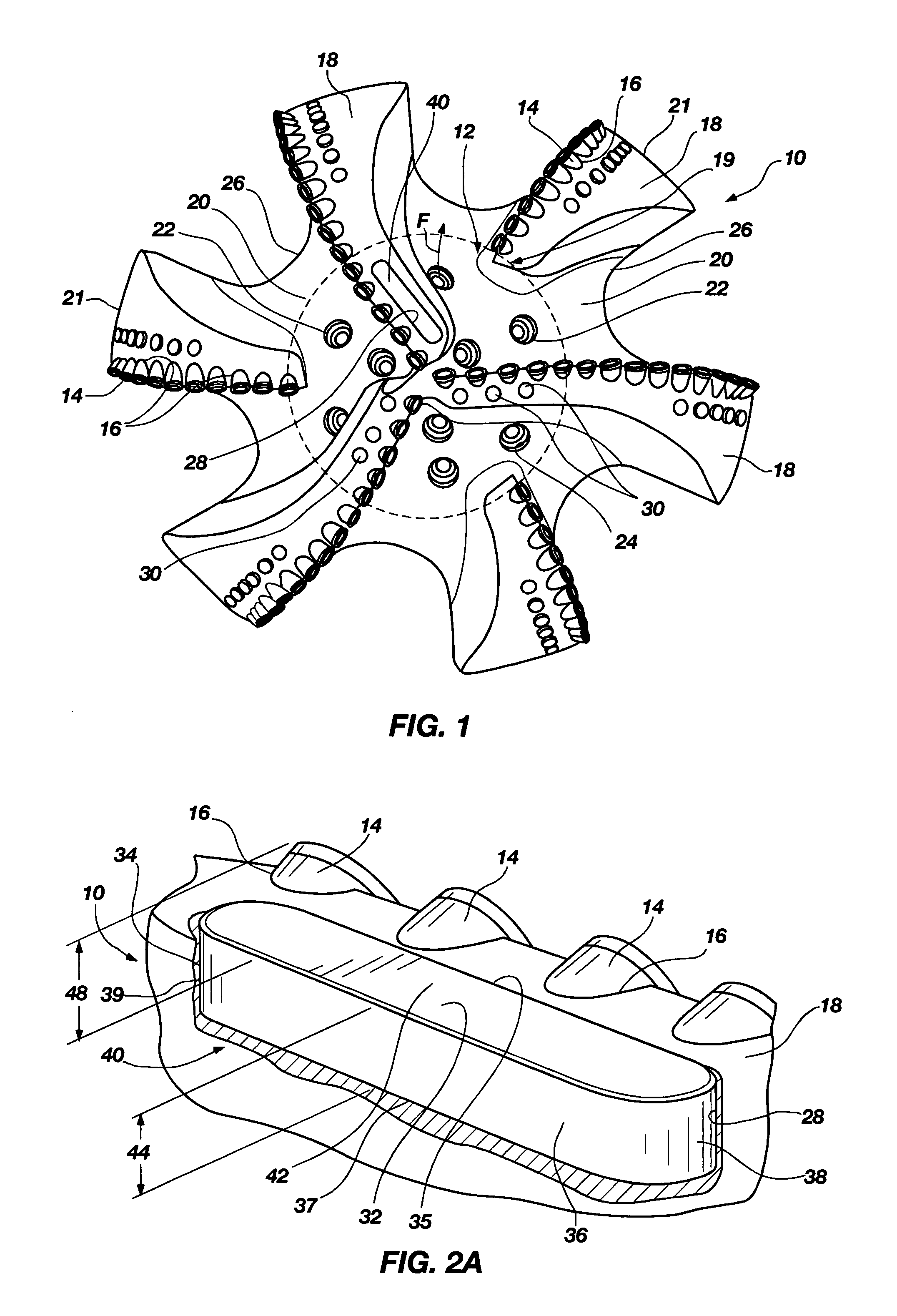
[0041]the invention is shown in FIGS. 1, 2A, 3A and 4. FIG. 1 shows a steel body drag bit 10 having an attached bearing block 40 as viewed by looking upwardly at its face or leading end 12 as if the viewer was positioned at the bottom of a borehole. Bit 10 includes a plurality of PDC cutters 14 bonded by their substrates (diamond tables and substrates not shown separately for clarity), as by brazing, into pockets 16 in blades 18 extending above the face 12 of the bit 10, as is known in the art with respect to the fabrication of steel body bits. Alternatively, the bit 10 may also be a so-called “matrix” type bit. Such bits include a mass of metal powder, such as tungsten carbide, infiltrated with a molten, subsequently hardenable binder, such as a copper-based alloy, for example the bit frame 110 shown in FIG. 5 as discussed below. It should be understood, however, that the invention is not limited to steel body or matrix-type bits, and bits of other manufacture may also be configure...

seventh embodiment

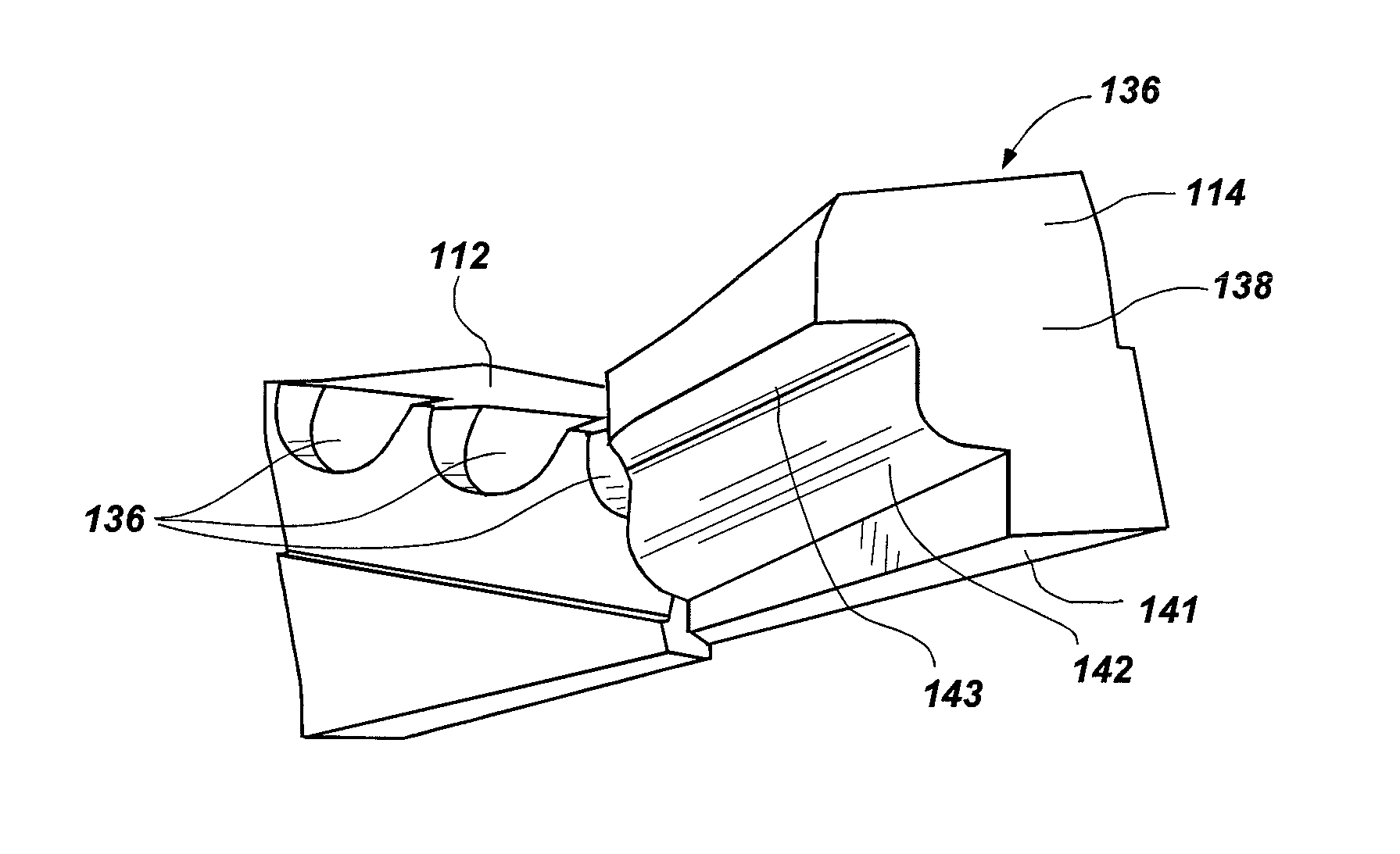
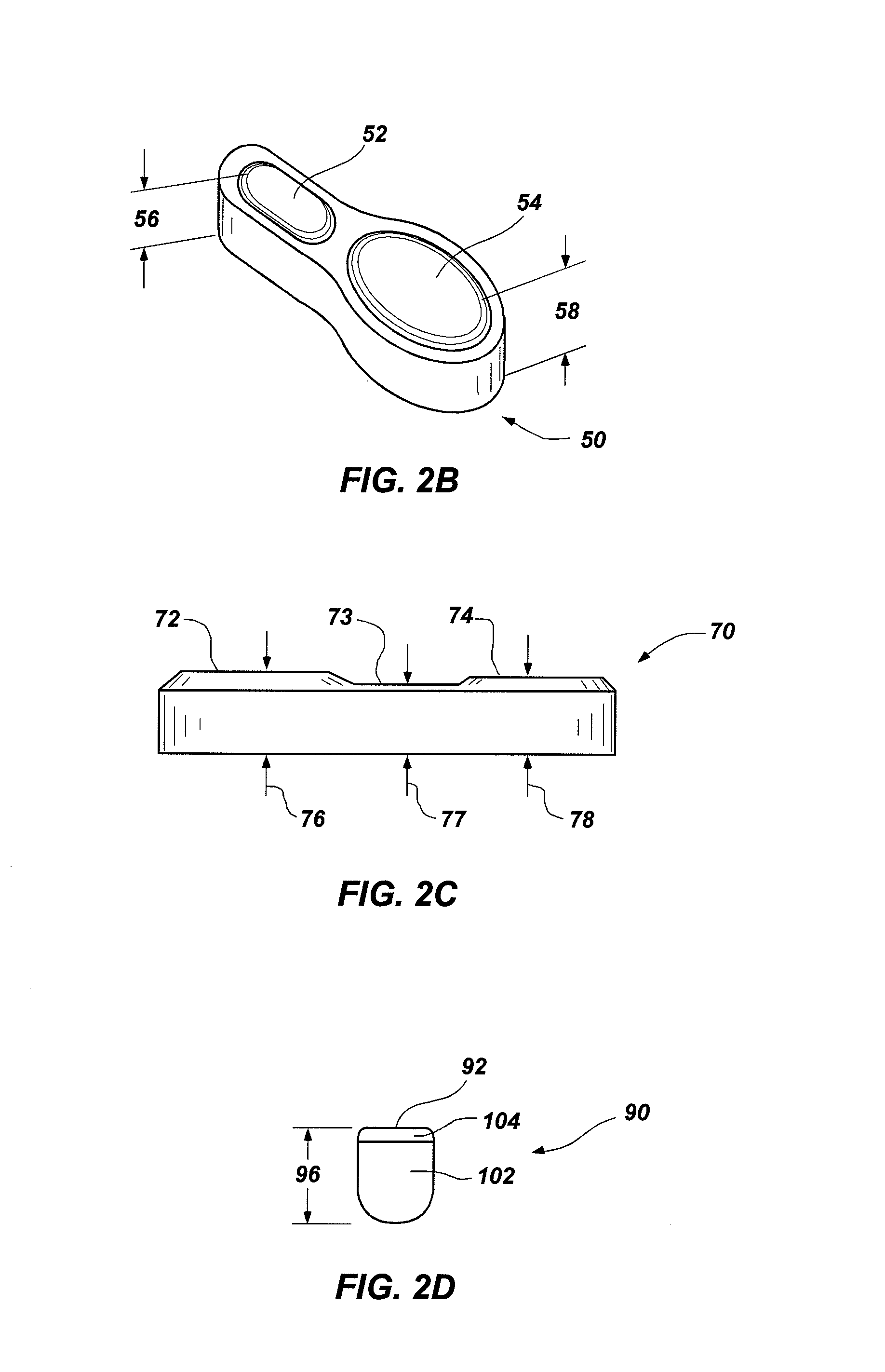
[0054]Interchangeable bearing blocks in accordance with a fifth, sixth and seventh embodiment of the invention are now presented. Generally, before turning specifically to the embodiments that follow, the bearing blocks of the invention may also include one or more cutter pockets. Each cutter pocket is in addition to the bearing block having a designed thickness and / or a designed rubbing area. Each cutter pocket added to the bearing block enables a target depth of cut (TDOC) for the cutters mounted in that block to be determined with respect to the block, instead of being determined conventionally with respect to the blade of a bit body as is known in the art. Also, each bearing block, as described in the embodiments that follow, may be configured to complete the radially inner end of a given blade portion and is located substantially in the cone region, the cone-nose region or the nose region of the bit frame. As mentioned above, bearing blocks having different thicknesses and diff...

fifth embodiment

[0056]FIG. 5 shows a bit frame 110 for a matrix body PDC bit, the bit frame 110 including attached cone blade bearing blocks 112, 114 in accordance with the invention. Simultaneous reference may also be made to FIGS. 6 and 7 to further describe embodiments of the invention. The bit frame 110 as depicted in FIG. 5 includes four blades 116, 117, 118, 119, and further includes a plurality of nozzle ports 120, a plurality of cutter pockets 122 and a plurality of insert pockets 124. The blades 116, 118 each include blade pockets 126, 128, respectively (blade pocket 128 shown also in FIG. 6). It is recognized that there may be any suitable number of blades or blade pockets on a given bit frame and are not necessarily limited to four blades 116, 117, 118, 119 and two blade pockets 126, 128, respectively. It is anticipated, although not necessarily required, that the bit frame may be standardized to include a blade pocket on each blade that extends radially inwardly significantly into the c...


PUM


Abstract

A bearing block is provided that may be used with a drag bit body or frame to limit depth of cut of cutters on a bit. The bearing block is designed so that it may be interchangeably replaced or repaired without necessitating alteration to a standardized bit frame. The interchangeable bearing block may be used to provide a target depth of cut (TDOC) and / or a selected contact or rubbing area to support weight on bit and limit depth of cut (DOC) for improving drilling performance of a bit. The interchangeable bearing block brings manufacturing selectability by providing a customizable product in terms of depth of cut selection and cutter penetration control for different formations, which is suitable for use with a common bit frame. A rotary drill bit assembly, a unitary cone insert bearing block for a drill bit, and a bit frame are also provided.

Description

FIELD OF THE INVENTION[0001]The present invention, in several embodiments, relates generally to a rotary fixed cutter or “drag” drill bit employing superabrasive cutters for drilling subterranean formations and, more particularly, to interchangeable bearing blocks useable in association with superabrasive cutters that provide improved accuracy for obtaining a target depth of cut for the cutters or a controlled bearing area on the face of the bit. A drill bit frame for receiving one or more interchangeable bearing blocks is also provided.BACKGROUND OF RELATED ART[0002]Rotary drag bits employing superabrasive cutting elements in the form of polycrystalline diamond compact (PDC) cutters have been employed for several decades. PDC cutters are typically comprised of a disc-shaped diamond “table” formed on and bonded under high-pressure and high-temperature conditions to a supporting substrate such as cemented tungsten carbide (WC), although other configurations are known. Bits carrying P...

Claims


Application Information

Patent Timeline
Patent Type & Authority Patents(United States)
IPC IPC(8): E21B10/55
CPCE21B10/42E21B10/62
Inventor ALIKO, ENISSCHWEFE, THORSTEN
Owner BAKER HUGHES HLDG LLC
Why Eureka
Try Eureka