
Optical measurment systems and methods

a measurement system and optical technology, applied in the field of optical measurement systems and methods, can solve the problems of insufficient sensitiveness of ellipsometry to certain electrical conditions, and achieve the effects of reducing undesirable process variations, reducing sensitivity, and accuracy and decorrelation of parameters

Inactive Publication Date: 2010-12-07
KLA TENCOR TECH CORP
View PDF4 Cites 18 Cited by
  • Summary
  • Abstract
  • Description
  • Claims
  • Application Information

AI Technical Summary

Benefits of technology

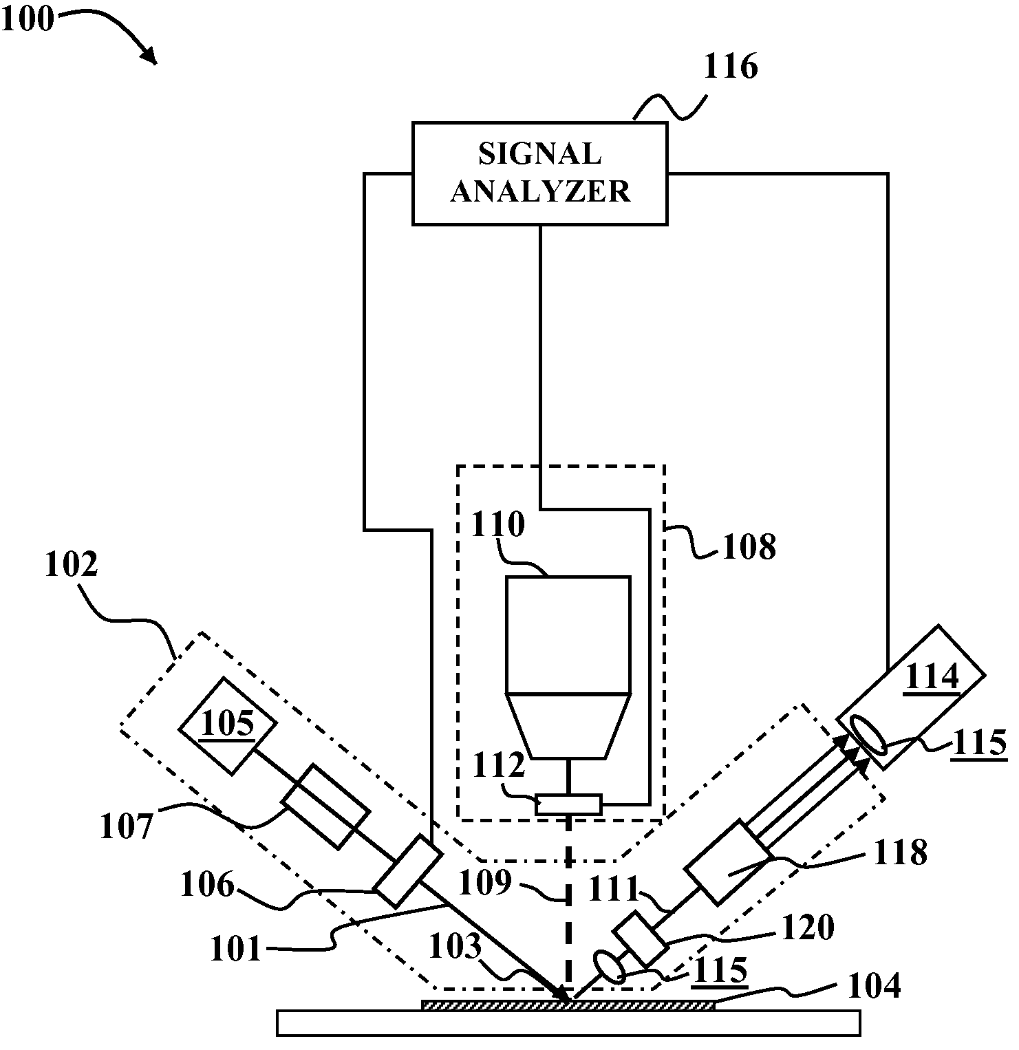
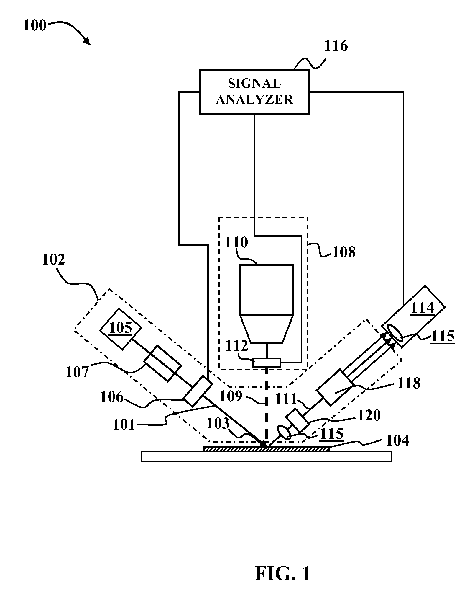
[0013]The ellipsometer 102 includes a rotating optical element 106 that is configured to modulate a polarization of the probe beam. By way of example, the rotating optical element may be a polarizer, e.g., Nichol prism, or the like in a rotating mount that rotates about an axis parallel to an optical axis of the probe beam 101. Rotation of the optical element 106 modulates the polarization of the probe beam 101. The use of rotating element 106 to modulate the polarization allows for lower frequency modulation of the polarization, e.g. at modulation frequencies ranging from about 1-5 Hz up to about 60 Hz.
[0016]In some embodiments of the invention, a synchronization signal generator may be coupled to the rotating element 106. The synchronization signal generator may be configured to generate a synchronization signal that depends upon rotation (e.g., frequency, phase, duty cycle, etc.) of the rotating element 106. The modulator 112 may be adapted to modulate the pump beam in response to synchronization signal. As a result, modulation of the pump beam may be synchronized to the rotation of the rotating element. As used herein, the term synchronized refers to a known or predictable relationship between a cycle of the pump modulation and a cycle of the rotation of the rotating element. Synchronization of the pump beam modulation and polarization rotation allows more accurate demodulation, especially if the separation between the two frequencies is not as large as might be desired.
[0024]In certain embodiments of the invention it may be desirable to separate the frequencies of the ellipsometer element rotation from the pump modulation frequency. To facilitate this, the modulation frequency may be either higher or lower than the rotation frequency. Considerable advantage may be obtained by modulating the pump at a much higher frequency than the ellipsometer, e.g., about 10 times higher or greater. The rapid modulation of the pump may allow for integration of the signal (or signals) detected by the detection system 114 over a cycle of rotation of the rotating element 106. This allows for greater sensitivity over a broader wavelength range without sacrificing precision or accuracy.
[0025]The optical system 108 may be configured to vary a modulation frequency of the pump beam 109 and determine a dependence of modulation intensity and phase on modulation frequency. The optical system 108 may also be configured to vary a duty cycle of the modulation of the pump beam and determine a dependence of the modulation signal on the duty cycle. By way of example, the modulator 112 may generate a reference signal that is synchronized to the modulation of the pump beam 109. The reference signal has a frequency that is the same as the modulation frequency or dependent on the modulation frequency in some known way. The duty cycle and phase of the reference signal may be the same as the duty cycle and phase of the pump beam modulation or may be dependent on the pump beam modulation phase and duty in some known way. The reference signal may be coupled to the detection system 114 and / or signal analyzer 116. The detection system 114 and / or signal analyzer 116 may be configured to integrate a signal from the detection system over a fraction of a rotation cycle of the rotating optical element 106, e.g. between about one sixteenth and about one quarter of the rotation cycle. Integrating the signal in this fashion allows for sensitivity over a broader wavelength range (e.g., 150 nm to about 800 nm) with sacrificing precision or accuracy. By way of comparison, conventional pump modulated ellipsometry using, e.g., a Pockels cell for probe beam polarization modulation can only provide sensitivity over a wavelength range roughly 30 to 40 nanometers wide.
[0043]Embodiments of the present invention provide increased sensitivity, accuracy and decorrelation of parameters as well as reduced effects of undesirable process variation.

Problems solved by technology

Ellipsometry is not sufficiently sensitive to certain electrical properties of materials such as band structure, mobility, trapped charge, etc.
Similarly, modulated reflectance (e.g., photoreflectance, electroreflectance, etc.) are able to measure some of these properties but are often not sensitive enough.

Method used


Image

  • Optical measurment systems and methods
  • Optical measurment systems and methods
  • Optical measurment systems and methods

Examples


Embodiment Construction

[0010]Although the following detailed description contains many specific details for the purposes of illustration, anyone of ordinary skill in the art will appreciate that many variations and alterations to the following details are within the scope of the invention. Accordingly, the exemplary embodiments of the invention described below are set forth without any loss of generality to, and without imposing limitations upon, the claimed invention.

[0011]Because conventional spectrometer designs limit the sampling rate, previous attempts to use ellipsometry as a detection mechanism have been limited to single wavelength operation and polarization modulated ellipsometry makes more sense in that case. Certain embodiments of the present invention, by contrast, utilize a novel spectrometer, which enables rotating element spectroscopic detection in conjunction with extraction of a pump-modulation-synchronized signal on a per-pixel basis over a broad wavelength range.

[0012]FIG. 1 depicts an ...


PUM


Abstract

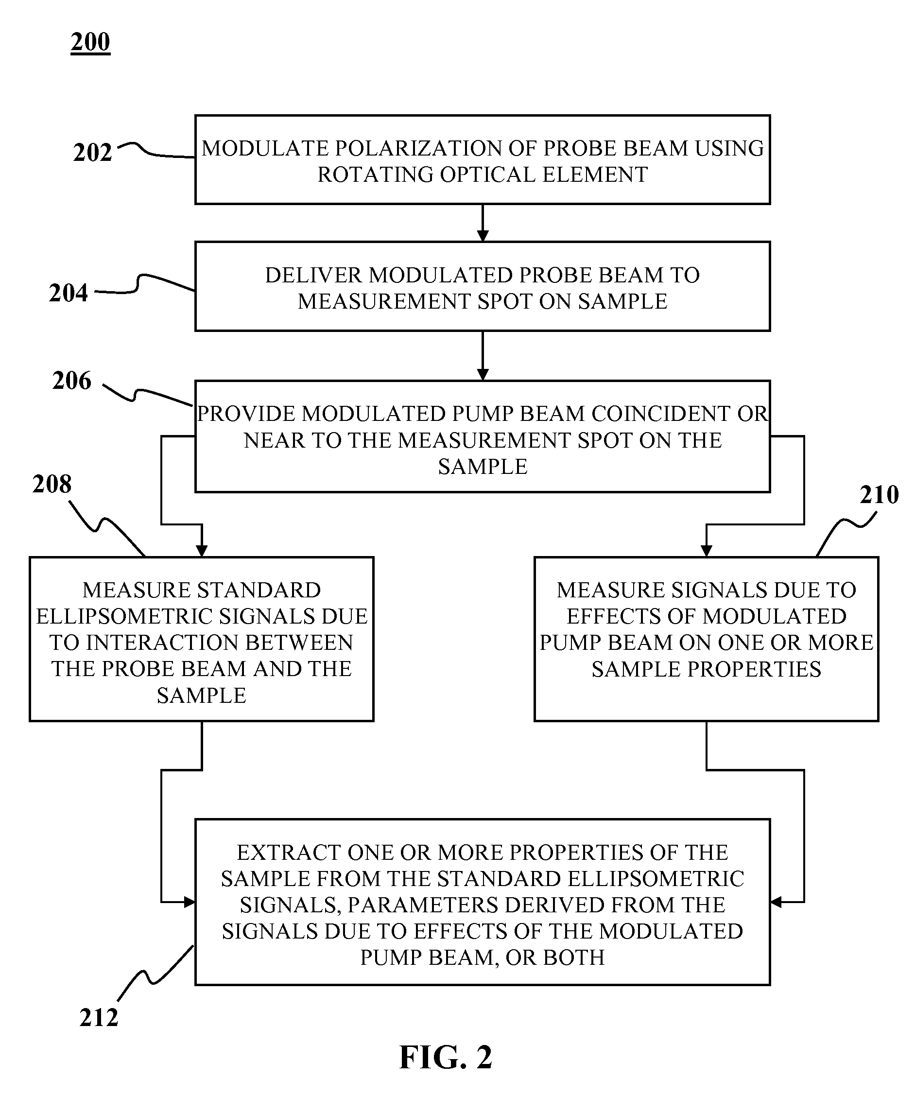
An optical measurement system includes a rotating element ellipsometer comprising a radiant source and a rotating optical element coupled to the radian source, an optical system to provide a modulated pump beam, a detection system optically coupled to the ellipsometer and a signal analyzer. The rotating element ellipsometer is configured to deliver a probe beam to a measurement spot on a sample and to measure one or more ellipsometric parameters of the sample at one or more discrete wavelengths or wavelength ranges, or a plurality of wavelengths across a wavelength range. Methods for determining sample characteristics from radiation scattered, reflected, diffracted or otherwise emitted from a sample surface using the optical measurement systems are also disclosed.

Description

FIELD OF THE INVENTION[0001]This invention generally relates optical measurement systems and methods and more particularly to systems and methods for determining sample characteristics from radiation scattered, reflected, diffracted or otherwise emitted from a sample surface.BACKGROUND OF THE INVENTION[0002]Ellipsometry is currently used for the measurement of film thickness, dielectric function and composition. Ellipsometry is not sufficiently sensitive to certain electrical properties of materials such as band structure, mobility, trapped charge, etc. Similarly, modulated reflectance (e.g., photoreflectance, electroreflectance, etc.) are able to measure some of these properties but are often not sensitive enough.[0003]It is within this context that embodiments of the present invention arise.BRIEF DESCRIPTION OF THE DRAWINGS[0004]Objects and advantages of the invention will become apparent upon reading the following detailed description and upon reference to the accompanying drawin...

Claims


Application Information

Patent Timeline
IPC IPC(8): G01J4/00
CPCG01N21/1717G01N21/211G01N21/47G01N2021/213
Inventor BEVIS, CHRISTOPHER F.
Owner KLA TENCOR TECH CORP
Learn More