Diesel particulate filter system for auxiliary power units

a technology of auxiliary power units and dpf systems, which is applied in the direction of electrical control, fluid pressure control, instruments, etc., can solve the problems of not being able to integrate dpf systems into apu's, being prohibitively expensive for drivers to idle engines for long periods of time, and saving more than $5,000 per year in fuel costs alon

Inactive Publication Date: 2010-12-14
GO GREEN APU
View PDF66 Cites 31 Cited by
  • Summary
  • Abstract
  • Description
  • Claims
  • Application Information

AI Technical Summary

Benefits of technology

[0002]The present invention is related to systems for reducing the emissions produced by an engine affixed to a body during operation and reducing noise and vibration. The present invention is particularly related to a small form factor active / passive Diesel Particulate Filter (DPF) system having an exhaust backpressure sensor, a heating element, a Diesel Oxidation Catalyst (DOC), a power relay switch, a filter and an electronic control unit for controlling the heating element based on backpressure detected by the sensor.STATEMENT AS TO THE RIGHTS TO INVENTIONS MADE UNDER FEDERALLY SPONSORED RESEARCH OR DEVELOPMENT

Problems solved by technology

With the current average price for a gallon of diesel gasoline around $2.37 per gallon and an idling engine consuming 1.2 gallons per hour, it is becoming prohibitively expensive for drivers to idle their engines for long periods of time.
A typical APU consumes between 0.2-0.3 gallons per hour, which saves more than $5,000 per year in fuel costs alone.
While it is known to include a DPF system on certain types of diesel engines, the need to incorporate DPF systems into APU's is a new problem and presents a number of different issues not previously addressed with DPF systems.
Smaller engines, such as those used for APU's do not typically generate sufficient exhaust temperatures to induce oxidation unassisted.
Active regeneration systems, however, are large and expensive, which make their incorporation into an APU impractical.
While the filters are large, and that can be problematic, the filters can be located remote from the APU on a portion of the truck chassis that affords more space.
Naturally, servicing the engine to clean out the filter adds complication to ownership of the engine and DPF system and increases the cost of operating the engine.
In addition to the need to decrease emissions levels, APU's are typically noisy to operate.
Even with a muffler installed on the exhaust system, they tend to output a significant level of noise and generate a significant amount of vibration throughout the cabin, especially when the engine is mounted under the cabin or attached to the frame rail of the truck.
Noise from the engine, however, also typically travels through the air intake system, through the engine, and back into the atmosphere.
In certain smaller engines, especially where the exhaust is in close proximity to the air intake, such as in an APU, noise traveling from the engine through the air intake can be a significant noise source.
However, having a filter placed in the upstream direction of the airflow near the silencer can also generate increased levels of noise.
While mufflers and intake silencers can reduce noise and effectively reduce some level of vibration, the aforementioned noise reduction techniques are not typically focused on vibration reduction which may still exist in the absence of noise being attenuated by the muffler or silencer mechanisms.
Furthermore, mufflers, DPF systems and other noise and vibration reduction technologies are often placed within the intake and exhaust systems of an engine, which can have an impact on airflow.
Since DPF systems often require back pressure within the exhaust to be tightly regulated to insure a sufficient quantity of particulate matter in the exhaust is removed, it can be difficult to reduce the sound and vibrations generated by an APU when a DPF system is installed because the introduction of the noise and vibration technology may impact the operability of the DPF system.

Method used


Image

  • Diesel particulate filter system for auxiliary power units
  • Diesel particulate filter system for auxiliary power units
  • Diesel particulate filter system for auxiliary power units

Examples


Embodiment Construction

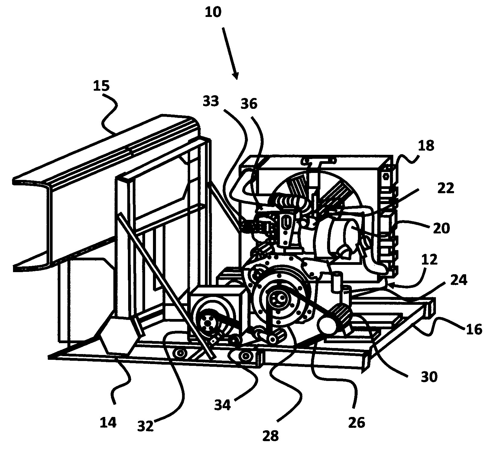
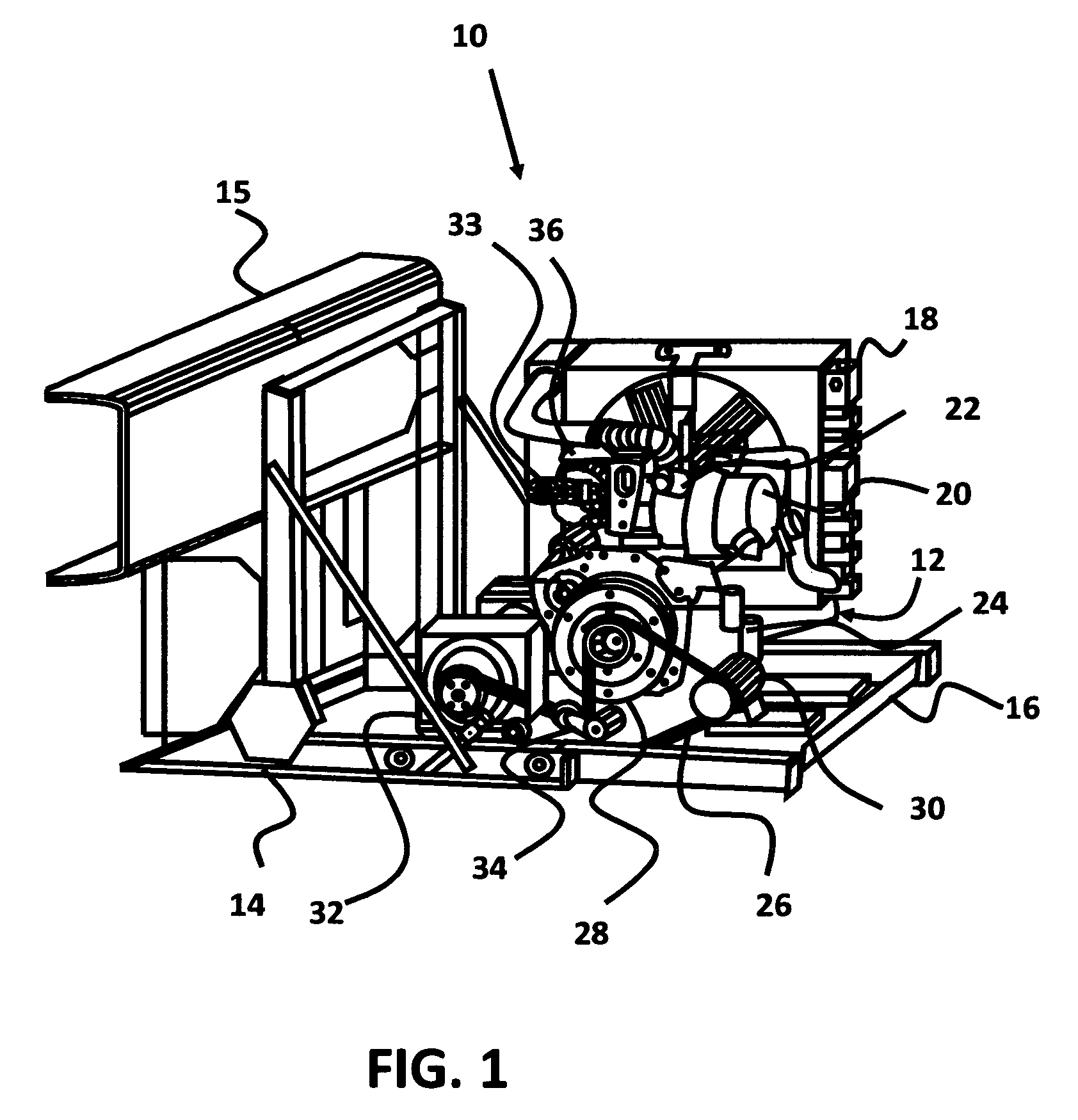
[0021]The present invention is related to a small form factor, active / passive diesel particulate filter (DPF) system for an auxiliary power unit (APU), and more particularly to a DPF system for connection to the exhaust system of an APU that also includes noise and vibration reduction components on the intake system.

[0022]Due to the structural integrity of the frame rails of a truck or similar vehicle, an APU is ideally mounted to one of the frame rails to provide a very stable mounting environment. The APU shown in FIG. 1 is mounted to a frame rail via a frame assembly. However, it is not always possible or feasible to mount the APU to the frame rails, so APU's are often mounted below or attached to the cabin of the truck. Mounting the APU close to the cabin can reduce the cost of the installation by reducing the length of the umbilical cord (primarily comprised of electrical lines) between the APU and the truck cabin where the main controller for the APU is located. At the same ti...


PUM

PropertyMeasurementUnit
surface areaaaaaaaaaaa
lengthaaaaaaaaaa
surface areaaaaaaaaaaa

Abstract

A system for reducing the emissions produced by an engine affixed to a body during operation and reducing noise and vibration. The present invention is particularly related to a small form factor active / passive Diesel Particulate Filter system having an exhaust backpressure sensor, a heating element, a Diesel Oxidation Catalyst, a power relay switch, a filter and an electronic control unit for controlling the heating element based on backpressure detected by the sensor.

Description

CROSS-REFERENCES TO RELATED APPLICATIONS[0001]This is a utility patent application, taking priority from provisional patent application Ser. No. 61 / 011,579, filed Jan. 17, 2008, which application is incorporated herein by reference, and a continuation-in-part of U.S. patent application Ser. No. 11 / 899,682, filed on Sep. 7, 2007.BRIEF DESCRIPTION OF THE INVENTION[0002]The present invention is related to systems for reducing the emissions produced by an engine affixed to a body during operation and reducing noise and vibration. The present invention is particularly related to a small form factor active / passive Diesel Particulate Filter (DPF) system having an exhaust backpressure sensor, a heating element, a Diesel Oxidation Catalyst (DOC), a power relay switch, a filter and an electronic control unit for controlling the heating element based on backpressure detected by the sensor.STATEMENT AS TO THE RIGHTS TO INVENTIONS MADE UNDER FEDERALLY SPONSORED RESEARCH OR DEVELOPMENT[0003]Not A...

Claims


Application Information

Patent Timeline
Patent Type & Authority Patents(United States)
IPC IPC(8): F01N3/00F01N5/04G05D16/00F02M35/10F02M35/00F02B77/08F02B63/04F01N1/08
CPCB60R13/0876B60R13/0884F01N3/0231F01N3/027F01N3/035F01N3/106F01N13/002F02D41/1448F01N2560/08F01N2590/06F02D41/22
Inventor SHAFF, RICHARDENGLISH, RAYMONDPICTON, EDWARD PATRICK
Owner GO GREEN APU
Why Eureka
Try Eureka