Detection of positive and negative ions

a positive and negative ion technology, applied in the field of ion detection, can solve the problems of reducing sensitivity, fouling, varying signal noise,

Active Publication Date: 2010-12-21
BRUKER DALTONIK GMBH & CO KG
View PDF37 Cites 28 Cited by
  • Summary
  • Abstract
  • Description
  • Claims
  • Application Information

AI Technical Summary

Problems solved by technology

Typically, the entrance into the signal multiplier is aligned on-axis with the incoming ion beam, which is disadvantageous in that neutral (uncharged) particles of no analytical value enter the ion detector and contribute to problems such as varying signal noise, reduced sensitivity, fouling, etc.
Consequently, the maximum switching speed is limited (typically 200-2000 ms) and the fast-switching circuitry required is complex and costly.
Ion detectors such as disclosed in U.S. Pat. Nos. 4,627,448 and Re 33,344 suffer from the disadvantages noted above in that they require complex and costly switching hardware and switching between polarities causes undesirable delay.
Additionally, these types of ion detectors do not adequately prevent neutral particles from entering the ion detector.
Re 33,344 and 4,066,894 also suffer from the disadvantages noted above in that they do not adequately prevent neutral particles from entering the ion detector.
Moreover, they do not adequately ensure that an acceptable number of ions of a given polarity strike the corresponding first dynode and are detected.
This type of ion detector is disadvantageous in that, like the other ion detectors mentioned above, the ion detector requires at least one conversion dynode.
Conversion dynodes require high acceleration voltages, are prone to producing a corona discharge, and contribute to background signal noise.

Method used


Image

  • Detection of positive and negative ions
  • Detection of positive and negative ions
  • Detection of positive and negative ions

Examples


Embodiment Construction

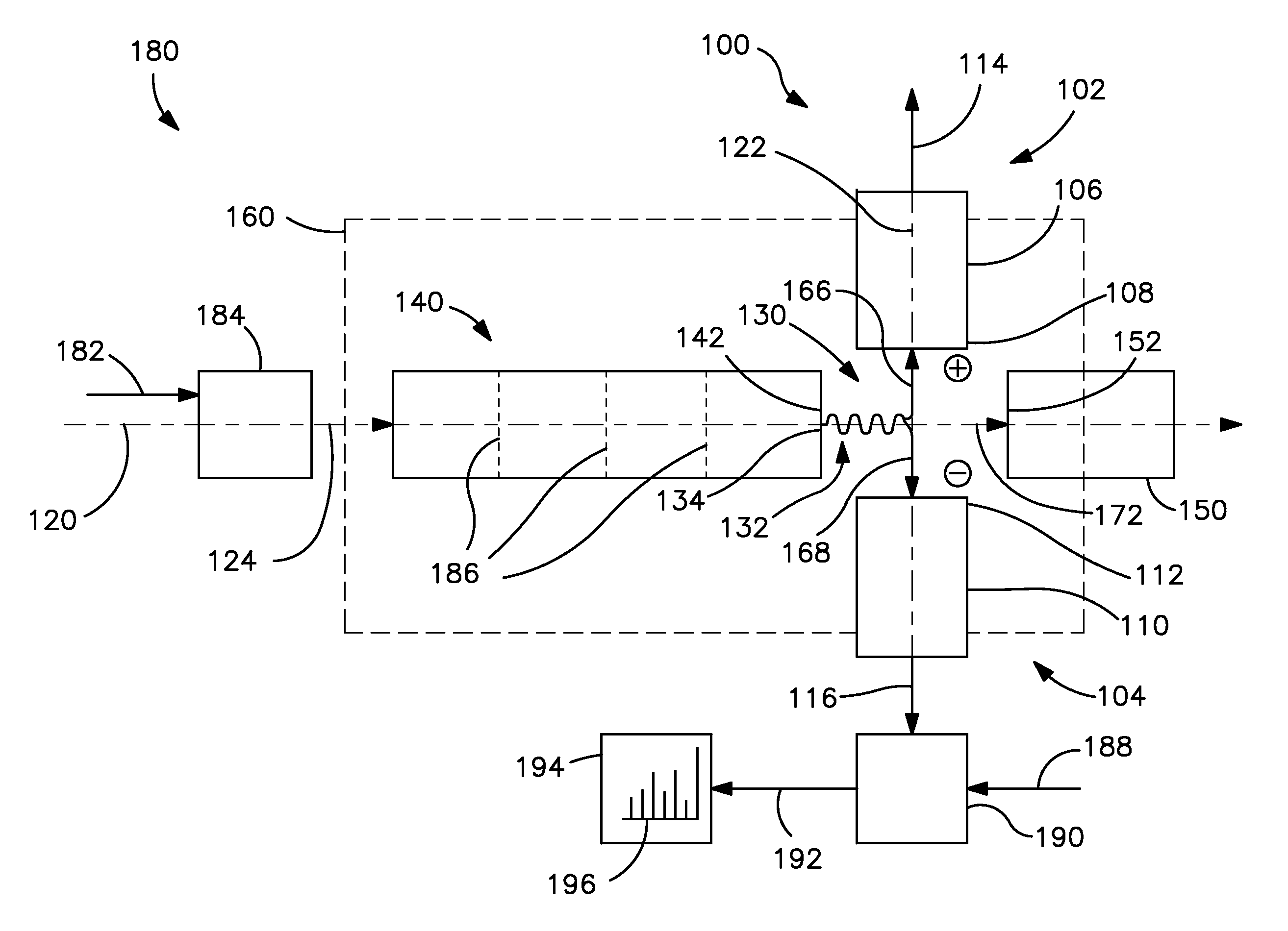
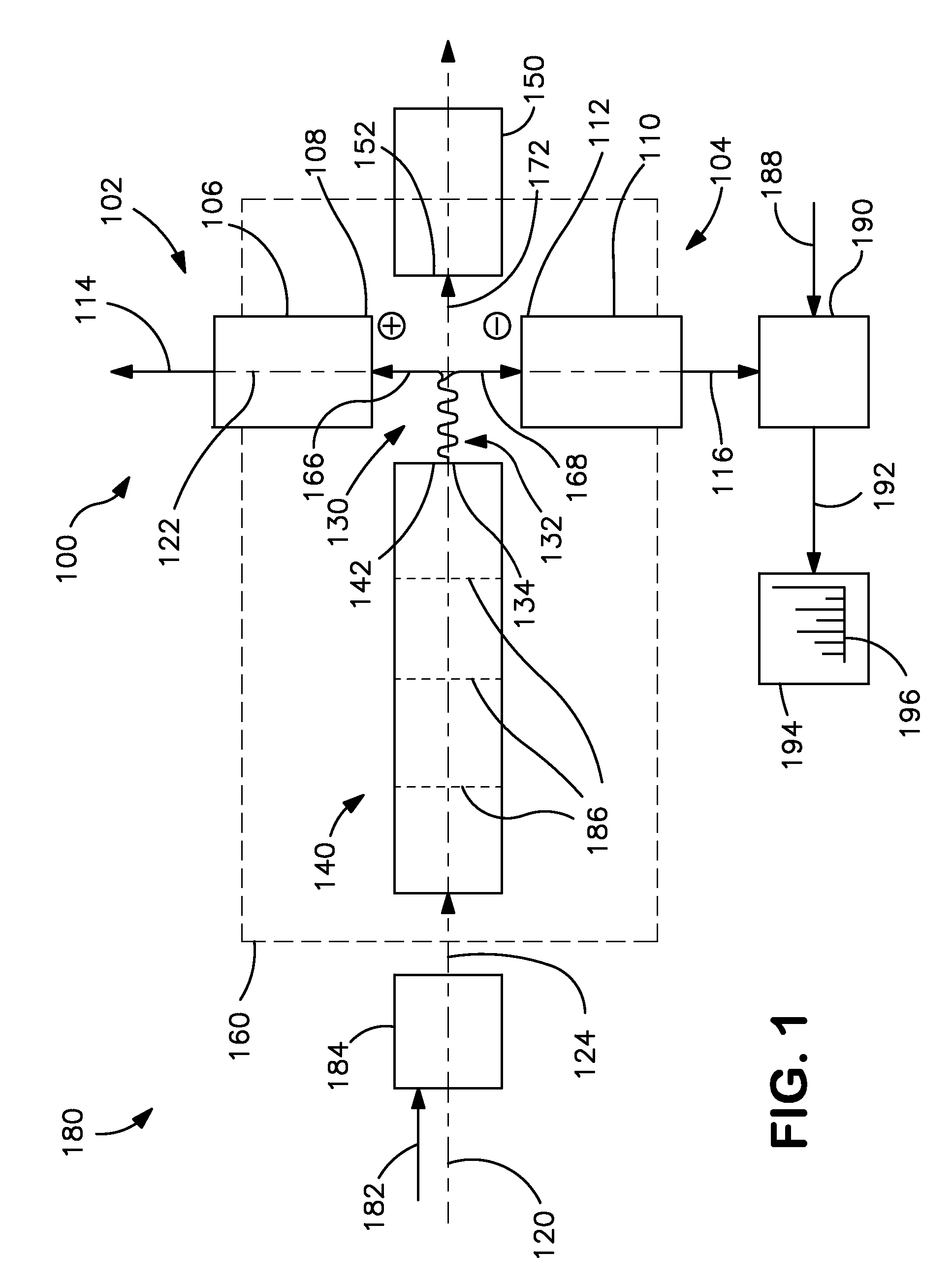
[0029]The subject matter disclosed herein generally relates to the detection of ions and associated ion processing. Examples of implementations of methods and related devices, apparatus, and / or systems are described in more detail below with reference to FIGS. 1-5. These examples are described in the context of mass spectrometry (MS). However, any process that involves the detection of ions may fall within the scope of this disclosure. Additional examples include, but are not limited to, vacuum deposition and other fabrication processes such as may be employed to manufacture materials, electronic devices, optical devices, and articles of manufacture.

[0030]FIG. 1 is a schematic view of an example of an ion detector (or ion detection apparatus, assembly, or system) 100 according to an implementation of the present disclosure. The ion detector 100 includes a first ion detection device or unit 102 and a second ion detection device or unit 104. One of the ion detection devices 102 or 104...


PUM


Abstract

An ion detector comprises an ion guide with electrodes arranged about a first axis; a positive ion detection device with an ion inlet at a first side of the ion output section offset from and at an angle to the first axis; and a negative ion detection device with an ion inlet at a second side opposite the first side, offset from and at an angle to the first axis. A negative voltage bias applied to the positive ion device accelerates positive ions toward the inlet along a path including a component along a second axis orthogonal to the first axis. A positive voltage bias applied to the negative ion detection device accelerates negative ions toward the inlet along a path that includes a component along the second axis orthogonal to the first axis in a direction generally opposite to the path of the positive ions.

Description

FIELD OF THE INVENTION[0001]The present invention relates generally to the detection of ions which finds use, for example, in fields of analytical chemistry such as mass spectrometry. More particularly, the present invention relates to selectively detecting positive or negative ions, including sequentially or simultaneously as desired.BACKGROUND OF THE INVENTION[0002]An ion detector is a type of transducer that converts ion current (ion flux, ion beam, etc.) to electrical current and thus is useful in technologies entailing the processing, transport, or manipulation of ions, such as for example mass spectrometry (MS), electronics fabrication, coating or surface treatment of articles of manufacture, etc. An ion detector is commonly employed in an MS system. Generally, an MS system converts the ionizable components of a sample material into ions and resolves (sorts, separates, or “analyzes”) the ions according to their mass-to-charge ratios, thereby producing an output of mass-discrim...

Claims


Application Information

Patent Timeline
Patent Type & Authority Patents(United States)
IPC IPC(8): H01J49/28H01J49/00
CPCH01J49/0095H01J49/025H01J49/063
Inventor STEINER, URS
Owner BRUKER DALTONIK GMBH & CO KG
Why Eureka
Try Eureka