Class H drive

a technology of actuator drivers and controllers, applied in the direction of motor/generator/converter stoppers, electronic commutators, dynamo-electric converter control, etc., can solve the problems of high frequency switching noise that can interfere with the operation of the device, and achieve the effect of employing these approaches

Inactive Publication Date: 2011-01-04
MENEGOLI PAOLO +1
View PDF17 Cites 64 Cited by
  • Summary
  • Abstract
  • Description
  • Claims
  • Application Information

AI Technical Summary

Benefits of technology

[0040]It is another objective of the present invention to provide a VCM driver that improves upon the efficiency of the motor drive while maintaining a linear amplifier approach for the output stage. The utilization of PWM or PSM (Phase Shift Modulation) switching approaches, such as driving a motor in class-D or with more traditional PWM control loops, introduces high frequency switching noise that can interfere with the operation of the device. In the case of the VCM, the Hard Disk Drive manufacturers are reluctant to employ these approaches despite of their advantages in terms of reduced power dissipation.
[0063]It is also noteworthy that the bridge common mode output voltage feedback allows excellent current control even in presence of varying BEMF, and in addition higher efficiency than the traditional class AB output stages can be obtained because the voltage across the low side output transistors conducting the motor current is minimized. It is also advantageous that the drains of the conducting low side drivers are regulated to be at a low voltage because this way excellent current regulation can be achieved independently from the high transconductance of the output device of the power current mirror.

Problems solved by technology

The utilization of PWM or PSM (Phase Shift Modulation) switching approaches, such as driving a motor in class-D or with more traditional PWM control loops, introduces high frequency switching noise that can interfere with the operation of the device.
In the case of the VCM, the Hard Disk Drive manufacturers are reluctant to employ these approaches despite of their advantages in terms of reduced power dissipation.

Method used


Image

  • Class H drive
  • Class H drive
  • Class H drive

Examples


Embodiment Construction

A. FIG. 2

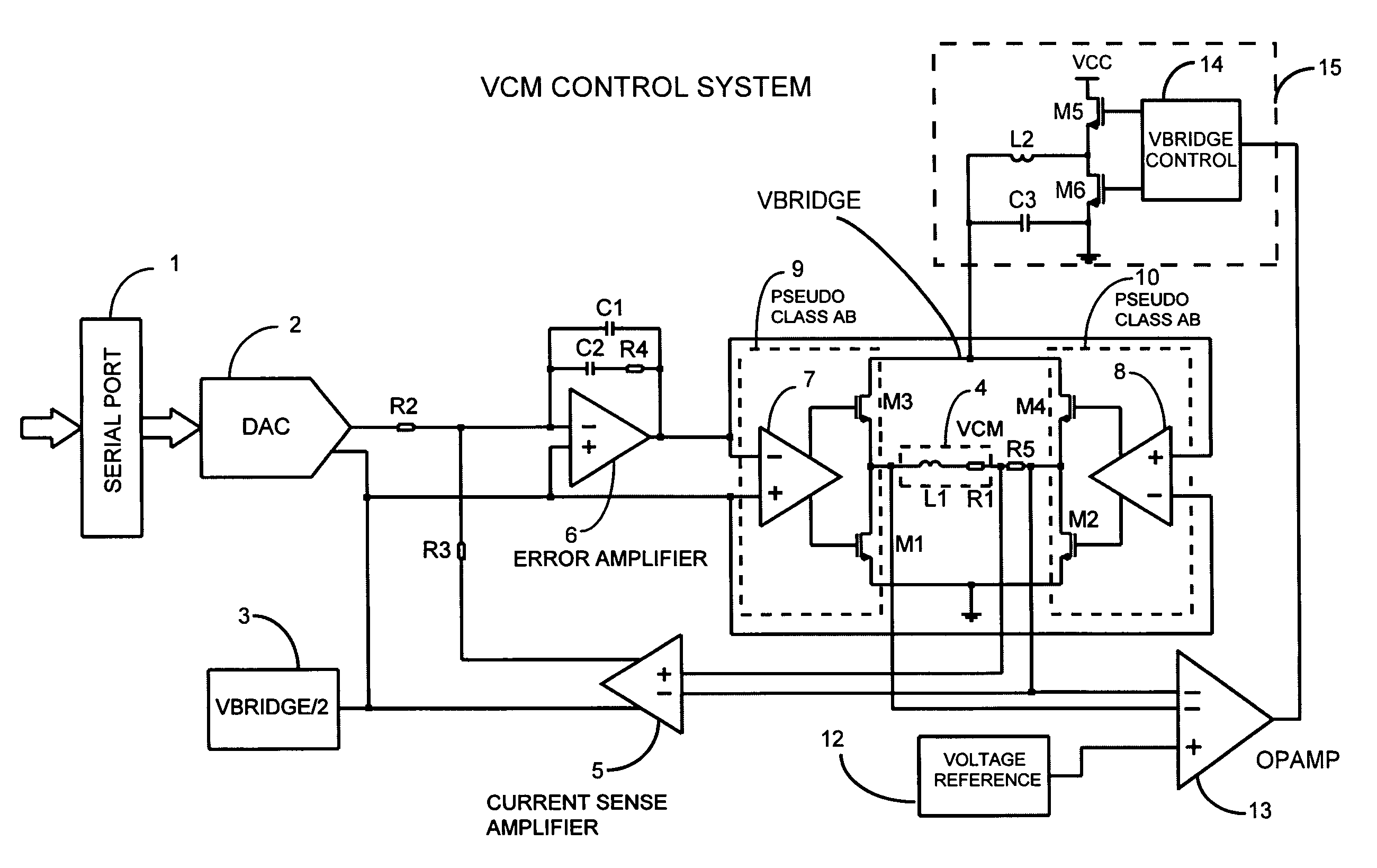
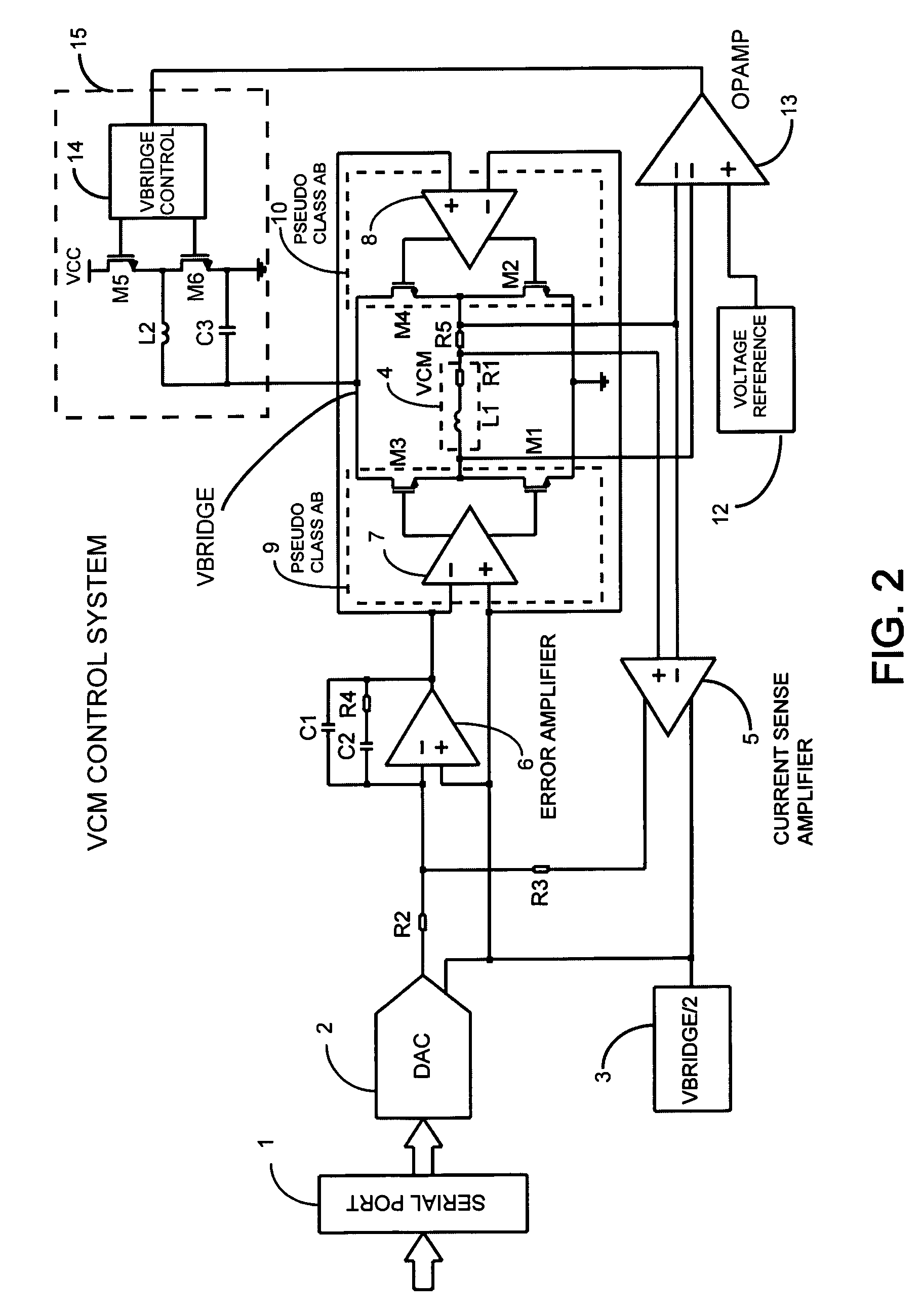
[0073]FIG. 2 shows a general embodiment for the basic VCM driver control system utilizing a class H drive system. The pseudo class AB stages 9 and 10 drive the gates of the low side power transistors M1 and M2, and the gates of the high side power transistors M3 and M4 electrically coupled to the bridge supply node designated as VBRIDGE. A switching power converter 15 provides power to the bridge.

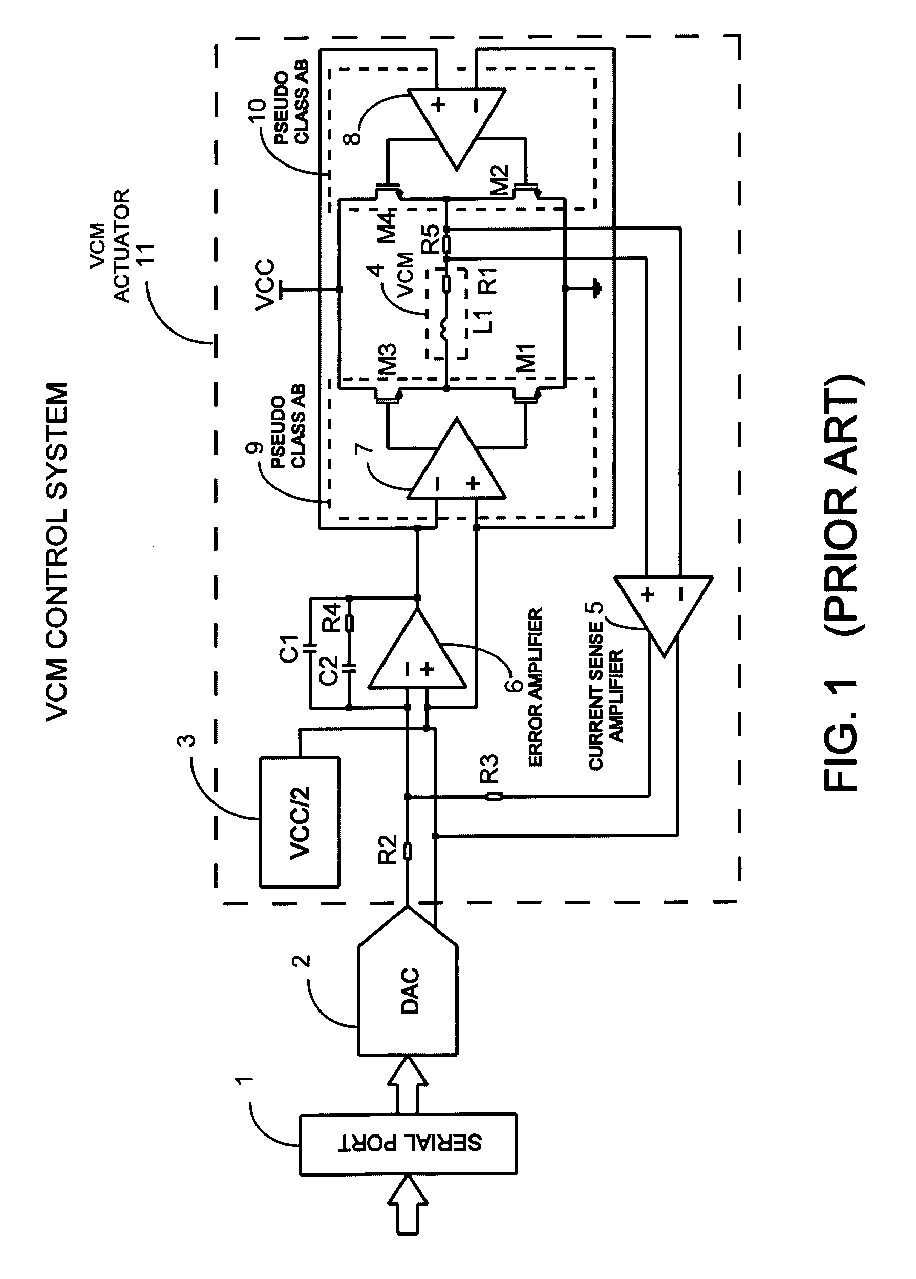
[0074]The embodiment of FIG. 2 is very similar to the classical implementation of the prior art described in FIG. 1, since there is an inner current control loop that regulates the load current sensed as the voltage drop on the resistor R5 and amplified by the operational amplifier 5. An error amplifier 6 drives the output power stage and operates to null the error signal defined as difference between the output of the sense amplifier 5 and the output of the DAC 2 whose input is fed by the serial port 1. A voltage reference 3 sets the output common mode voltage. In this configurati...


PUM


Abstract

A method for driving a load by using an output stage amplifier in full bridge configuration whose supply is modulated by means of a fast switching power converter, controlled in order to maintain the stage's output common mode at its minimum voltage, is presented. The modulation of the switching power converter output is obtained by a feedback control system regulating directly the voltage of the bridge output stage terminals. This bridge unipolar class H stage allows driving the load with high accuracy and improved efficiency without introducing switching noise and EMI at the load terminals typical of PWM driving. This method can be applied with the same benefits to class AB, pseudo class AB or to class A output stages. When this method is associated with an imposed current driving approach and with a current oversampling digital to analog converter the resulting advantages are very significant for accurate motor control applications.

Description

RELATED APPLICATION DATA[0001]The present application claims priority from U.S. Provisional Patent Application No. 60 / 934,613 for “CLASS H DRIVE” filed on Jun. 15, 2007.BACKGROUND OF THE INVENTION[0002]1. Field of the Invention[0003]The present invention is in the field of high efficiency amplifiers. The present invention is also in the field of actuator drivers and controllers. The present invention further relates to motor controllers. The present invention further relates to Hard Disk Drives and optical data storage devices. The present invention further relates to methods and circuits for controlling a voice coil motor for positioning the read / write head of a hard disk drive. The implementation is not limited to a specific technology, and applies to either the invention as an individual component or to inclusion of the present invention within larger systems which may be combined into a larger integrated circuit.[0004]The invention also falls within the field of integrated circu...

Claims


Application Information

Patent Timeline
Patent Type & Authority Patents(United States)
IPC IPC(8): H02P6/00
CPCG11B21/02H03F3/2173H03F1/0227
Inventor MENEGOLI, PAOLOSAWTELL, CARL
Owner MENEGOLI PAOLO
Why Eureka
Try Eureka