Fully differential non-inverted parallel amplifier for detecting biology electrical signal

a parallel amplifier and fully differential technology, applied in the direction of amplifier combinations, diagnostics, diagnostic recording/measuring, etc., can solve the problems of weak first amplifier gain, long time, and weak biology electrical signals, and achieve low cost, high efficiency, and simplified the design of biology electrical front-end circuits.

Active Publication Date: 2011-01-04
EDAN INSTR
View PDF6 Cites 24 Cited by
  • Summary
  • Abstract
  • Description
  • Claims
  • Application Information

AI Technical Summary

Benefits of technology

[0007]Aiming at the shortcomings above in existing technology, this invention is to provide a fully differential non-inverting parallel amplifier for detecting biology elect

Problems solved by technology

In this connection, an amplifier has to be used because of strong interference (power-frequency interference especially).
Unfortunately, biology electrical signals are usually weak and have to be amplified hundreds times or more.
In addition, polarizing voltage is generated when electrode touches skin, which makes the first gain of amplifier weak.
However, because of time constant circuits, the capacitors shall be charged when patients' polarizing voltage is high which makes the first output saturated.
As if the patient is in a stable state (the maximum polarizing voltage reaches a low normal value), then it needs a very long time to release the charge of stop capacitor, which makes it is impossible to gather ECG signal during this period.
So the communication device is slow in generating signals and its base line is easy to be shifted but slow to be recovered.
Firstly, the circuits

Method used


Image

  • Fully differential non-inverted parallel amplifier for detecting biology electrical signal
  • Fully differential non-inverted parallel amplifier for detecting biology electrical signal
  • Fully differential non-inverted parallel amplifier for detecting biology electrical signal

Examples


Embodiment Construction

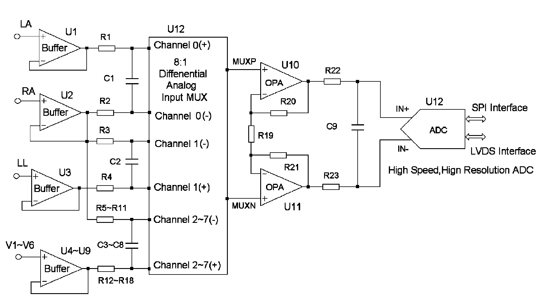
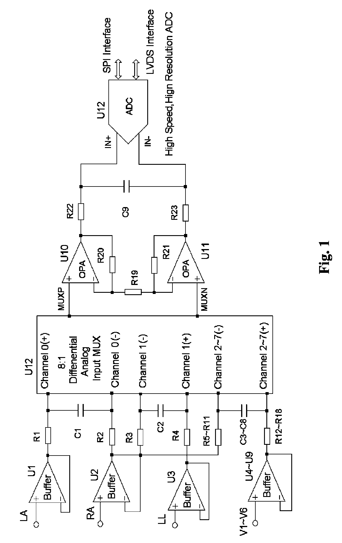
[0017]Further explanation to the invention is stated below combining with the attached figures:

[0018]Referring to FIG. 1, this fully differential non-inverting parallel amplifier for detecting biology electrical signal, including input buffer circuits, differential RC circuits, channel selector, non-inverting parallel amplifying circuits and analog-digital circuits. The biology electrical signal, first impeded and converted by the input buffer circuits, and then low-pass filtered by the differential filter circuits, shall be amplified with its common mode signal rejected by passing through the data selector and non-inverting parallel amplifier circuits. At last, the amplified biology electrical signal is output by analog to digital conversion in the analog-digital circuits after its noises beyond signal high frequency band are filtered by anti-aliasing filter net.

[0019]The input buffer has nine circuits U1-U9. Each circuits is comprised by gas discharge tube, current limiting resist...


PUM


Abstract

This invention relates to a fully differential non-inverting parallel amplifier for detecting biology electrical signal, including input buffer circuits, differential filter circuits, data selector, non-inverting parallel amplifying circuits and analog-digital circuits. The biology electrical signal, first impeded and converted by the input buffer circuits, and then low-pass filtered by the differential filter circuits, shall be amplified with its common mode signal rejected by passing through the data selector and non-inverting parallel amplifier circuits. At last, the amplified biology electrical signal is output by analog to digital conversion in the analog-digital circuits after its noises beyond signal high frequency band are filtered by anti-aliasing filter net. This invention, with low noise and high common mode rejection ratio, stable baseline, large signal input dynamic range, is reliable and not easy to be saturated. Furthermore, it can support mature PACE Detecting with a low cost. It is notable in social and economical benefits for its simple electrical circuits and easy use in any biology electrical testing equipments and controlling system.

Description

TECHNICAL FIELD[0001]The invention relates to a device for detecting biology electrical signal, in particular, a fully differential non-inverting parallel amplifier for detecting biology electrical signal.BACKGROUND ART[0002]It is well known that all biology electrical signal testing are carried out in a circumstance of strong background interference or existing patient pillaring voltage. In this connection, an amplifier has to be used because of strong interference (power-frequency interference especially). Unfortunately, biology electrical signals are usually weak and have to be amplified hundreds times or more. In addition, polarizing voltage is generated when electrode touches skin, which makes the first gain of amplifier weak. Then a second amplifying has to be carried out after isolating polarizing voltage by resistance-capacitance circuits. However, because of time constant circuits, the capacitors shall be charged when patients' polarizing voltage is high which makes the fir...

Claims


Application Information

Patent Timeline
IPC IPC(8): H03F3/45
CPCA61B5/0428H03F3/45475H03F3/45928H03F3/68A61B5/7203H03F2200/261H03F2203/45134H03F2203/45138H03F2203/45528A61B5/30A61B5/305
Inventor XIANG, XIAOFEIHU, XUNQIAOXIE, XICHENG
Owner EDAN INSTR
Why Eureka
Try Eureka