
Method of analyzing DNA sequence using field-effect device, and base sequence analyzer

a field-effect device and dna sequence technology, applied in the field of biotechnology, can solve the problems of large amount of base sequence data accumulating, large system cost, and low selectivity of reaction results

Active Publication Date: 2011-02-15
NAT INST FOR MATERIALS SCI
View PDF20 Cites 201 Cited by
  • Summary
  • Abstract
  • Description
  • Claims
  • Application Information

AI Technical Summary

Benefits of technology

This approach allows for precise DNA sequencing without the need for expensive optical systems or fluorescent labeling, improving sensitivity and accuracy while enabling efficient analysis of multiple genes in parallel.

Problems solved by technology

Under these circumstances, vast amounts of base sequence data are accumulating.
This requires lasers and complex optical systems, which causes the system to be large and expensive.
Most DNA microarrays now under development is based on a fundamental principle of detecting double-stranded DNAs by hybridization; thus, the selectivity of reaction is not very high and the accuracy needs improvement.
Moreover, the base sequence analysis based on electrophoresis involves complicated preparation of samples and requires large equipment since high voltage and optical detection units are usually required.
This hinders gene detection and decreases detection accuracy.
Since the electrode reaction is irreversible and non-equilibrium, corrosion of the electrode, generation of gasses, separation of immobilized nucleic acid, and degradation of stability of current measurement would result.
Thus, detection accuracy is degraded especially when measurement is repeated.
However, DNA probes formed on a substrate are inherently negatively charged; thus, the change in charge by hybridization with target DNAs is so small that it cannot be distinguished from nonspecific adsorption.
Furthermore while detecting a minute difference (a difference of one base) between two genes is required in the case of single nucleotide polymorphism (SNP), the sensitivity and accuracy (selectivity) of this technology are unsatisfactory and detection is difficult.
Moreover, according to a method based on a fundamental principle of hybridization only as in the case of DNA microarrays described above, it is impossible to analyze base sequence of target genes (DNA sequencing).
However, the system requires application of high voltage and an optical system for fluorescence detection and is not different from conventional electrophoresis regarding the fundamental principle.
Thus, problems of size, simplicity, economy, etc., still exist.
This method is relatively simple and suitable for small-size systems; however, the chemical reaction system is complex and parallel analysis of a large number of genes different from one another is difficult (Nonpatent document 6).
The distance between adjacent bases in the DNA molecule is 0.34 nm; thus, according to this method, it is difficult to analyze the base sequence by individually identifying the adjacent bases.
This technology is also of a kind that detects a signal based on complementary binding of DNAs; thus, the base sequence cannot be analyzed.

Method used


Image

  • Method of analyzing DNA sequence using field-effect device, and base sequence analyzer
  • Method of analyzing DNA sequence using field-effect device, and base sequence analyzer
  • Method of analyzing DNA sequence using field-effect device, and base sequence analyzer

Examples


example 1

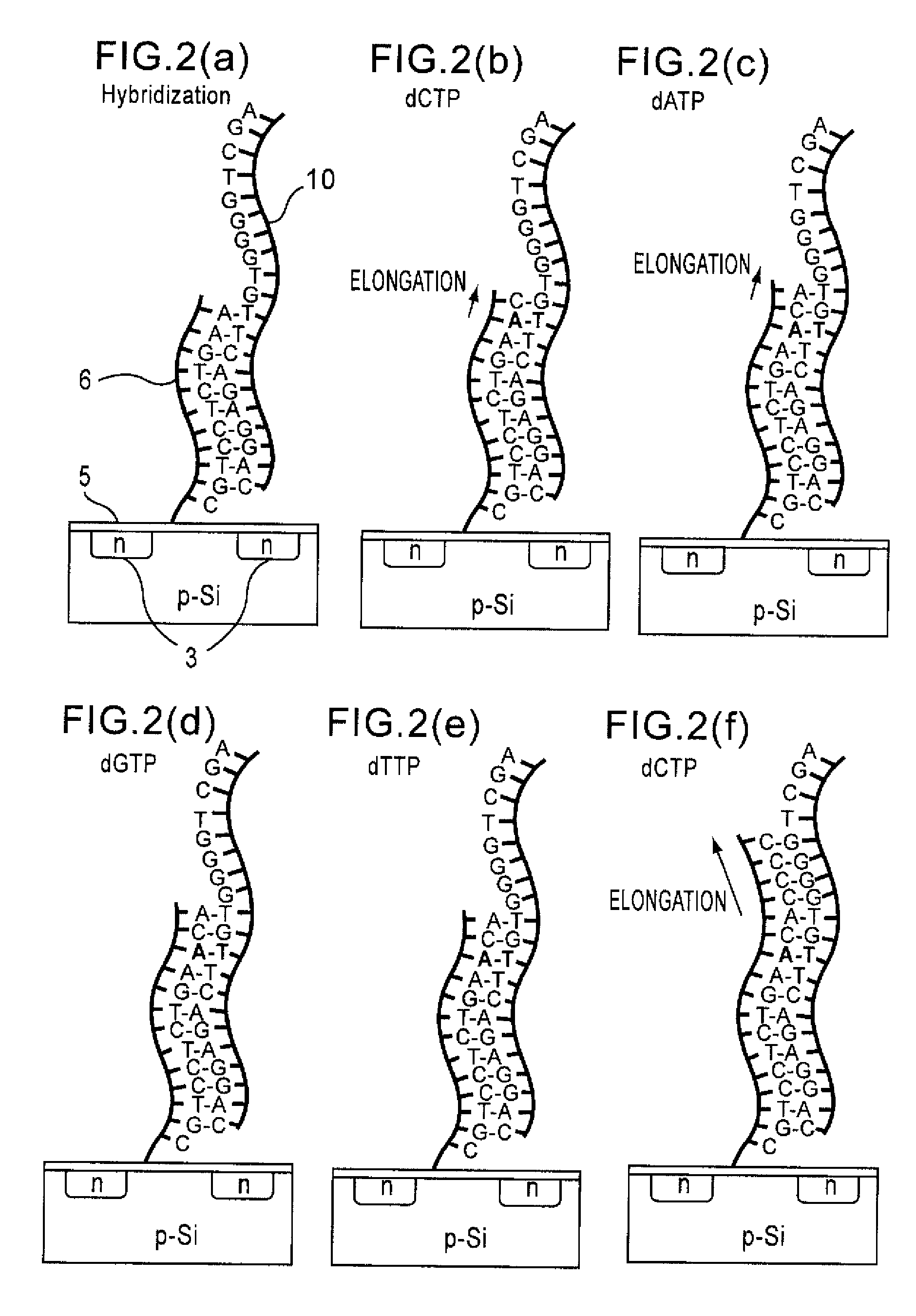
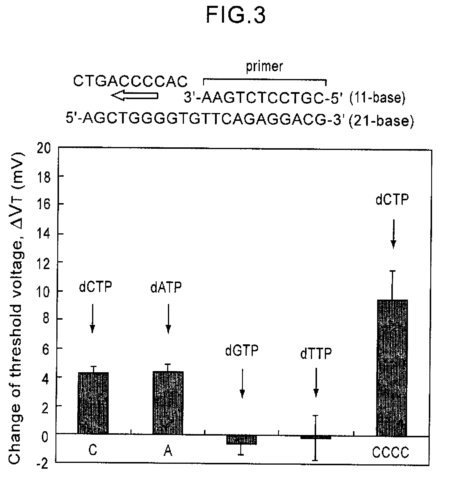
[0059]The base sequence of the R353Q region of a blood coagulation factor, factor VII gene (SEQ ID NO: 8) was analyzed according to the process of the present invention. A nine-base long oligonucleotide probe was immobilized on the gate insulating film of the gene transistor. After hybridization with the target DNA, enzyme, Taq DNA polymerase and substrates, dATP, dGTP, dCTP, and dTTP were sequentially added, resulting in SEQ ID NO: 9. The observed threshold voltages of the gene transistor after addition of each substrate are shown in FIG. 7. FIG. 7 shows that the threshold voltage changes with addition of complementary bases, C, C, A, C, G, and T to the base sequence of the target DNA. FIG. 7 also shows that a threshold voltage change about three times greater in magnitude is observed by addition of G for the sequence having three cytosines in a row. In this manner, the base sequence of the R353Q region of the factor VII gene can be read.

examples 2 and 3

[0060]The base sequences of C282Y region (Example 2) (SEQ ID NO: 10) and H63D region (Example 3) (SEQ ID NO: 12) of a hereditary hemochromatosis gene were analyzed as in Example 1. The results are shown in FIGS. 8 and 9. In this example also, dATP, dGTP, dCTP, and dTTP were sequentially added, resulting in SEQ ID NO: 11 and SEQ ID NO: 12, respectively. Changes in threshold voltage were observed if the substrate was complementary to the base sequence of the target DNA. If not, no change in threshold voltage was observed. Moreover, when the same bases existed two in a row, a larger change in threshold voltage was observed compared with the case of only one base. Thus, the base sequence of the DNA can be analyzed without labeling according to the method of the present invention.


PUM

PropertyMeasurementUnit
distanceaaaaaaaaaa
constant voltageaaaaaaaaaa
thicknessaaaaaaaaaa

Abstract

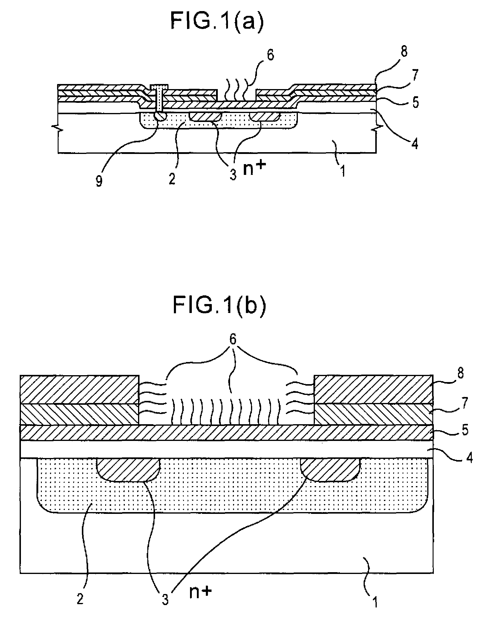
Since conventional DNA sequence analyzing technologies are based on the fundamental principle of fluorescent detection, expensive, complex optical systems and laser sources have been necessary.A field-effect device for gene detection of the present invention analyzes a base sequence by immobilizing a single-strand nucleic acid probe at a gate portion, inducing hybridization at the gate portion to form a double-stranded DNA, inducing elongation reaction by adding a DNA polymerase and one of the substrates, and measuring the electrical characteristic of the field-effect device caused by elongation reaction.Since the elongation reaction of one base induced at the gate portion can be directly converted to an electrical signal, expensive lasers or complex optical systems are not needed. Thus, a small gene polymorphism detection system that can conduct measurement at high precision can be provided.

Description

TECHNICAL FIELD[0001]The present invention relates to fields of biotechnology such as genetic diagnosis, DNA sequence analyses, and polymorphism analyses, and, in particular, to a technology in the field of gene analyses. To be more specific, the present invention relates to a method for analyzing base sequence of nucleic acids using a field-effect device for gene detection that can analyze the base sequence of a nucleic acid without labeling with a fluorescent dye or radioisotope and an analyzer that uses the method.BACKGROUND ART[0002]Decoding of the entire base sequence of human genome is ended and decoding of genomic base sequences of other living organisms is under rapid progress. Under these circumstances, vast amounts of base sequence data are accumulating. Gene-related technologies are expected to dramatically develop in a wide range of fields including various disease diagnosis, drug development, breeding of agricultural crops, etc., as the functions of genes in vivo are el...

Claims


Application Information

Patent Timeline
Patent Type & Authority Patents(United States)
IPC IPC(8): C12Q1/68C07H21/02C07H21/04
CPCB01L7/00G01N27/4145B01L3/5027B01L2200/12B01L2300/0645B01L2300/0877B01L2300/0636
Inventor MIYAHARA, YUJISAKATA, TOSHIYA
Owner NAT INST FOR MATERIALS SCI
Learn More