Zirconium dioxide luminescence oxygen sensor

a luminescence oxygen and sensor technology, applied in the field of zirconium dioxide luminescence oxygen sensor, can solve problems such as complex structure, and achieve the effects of simple measurement data handling, clear algorithm, and elimination of the need to stabilize temperatur

Inactive Publication Date: 2011-02-15
INST WYSOKICH CISNIEN POLSKIEJ AKADI NAUK
View PDF3 Cites 0 Cited by
  • Summary
  • Abstract
  • Description
  • Claims
  • Application Information

AI Technical Summary

Benefits of technology

[0019]The invention enables the simultaneous measurement of the oxygen amount in gases and the sensor temperature, what eliminates the necessity to stabilize the temperature and use of a temperature control device. The sensor working temperature can be regulated by the selection of the size of the nanocrystalline grains ZrO2 and in case of the use of small zirconium oxide crystals the sensor can work in temperatures above 100° C. The invention enables the determination of the amount of oxygen in hot gases as well as the determination of temperature of those gases. Furthermore, the way of measurement in accordance with the invention, is characterized by clear algorithm and relatively simple measurement data handling. In case of the luminescent sensor ZrO2 of the tetragonal phase, on account of low electric conduction, the heating element can be placed directly on ZrO2 by the method of the thin film settlement. In the measurement method, the performance of only two measurements in one stimulated cycle, in order to determine the partial pressure of oxygen in gas and the sensor temperature, is required.

Problems solved by technology

The principle of operation of the above-mentioned sensors is connected with the electric current conduction, what is disadvantageous to certain solutions.
(a) a device delivering measured gases, sensor sample chamber, in which the luminescence is being excited, and the fading time of which reflects the concentration of oxygen in gases; (b) a converter equipped with the source of light for the stimulation of the compound capable of luminescence in the sensor and sensitive light detector for the processing of emitted energy from the luminescent compound during the luminescence decay, which is being processed in the electric signal indicating the oxygen concentration in monitored gases, and (c) subsystems for the keeping of constant temperature of the sensor and processing of signal generated by the sensitive light detector. The disadvantage of the above-described solutions is complex structure.

Method used


Image

  • Zirconium dioxide luminescence oxygen sensor
  • Zirconium dioxide luminescence oxygen sensor
  • Zirconium dioxide luminescence oxygen sensor

Examples


example 1

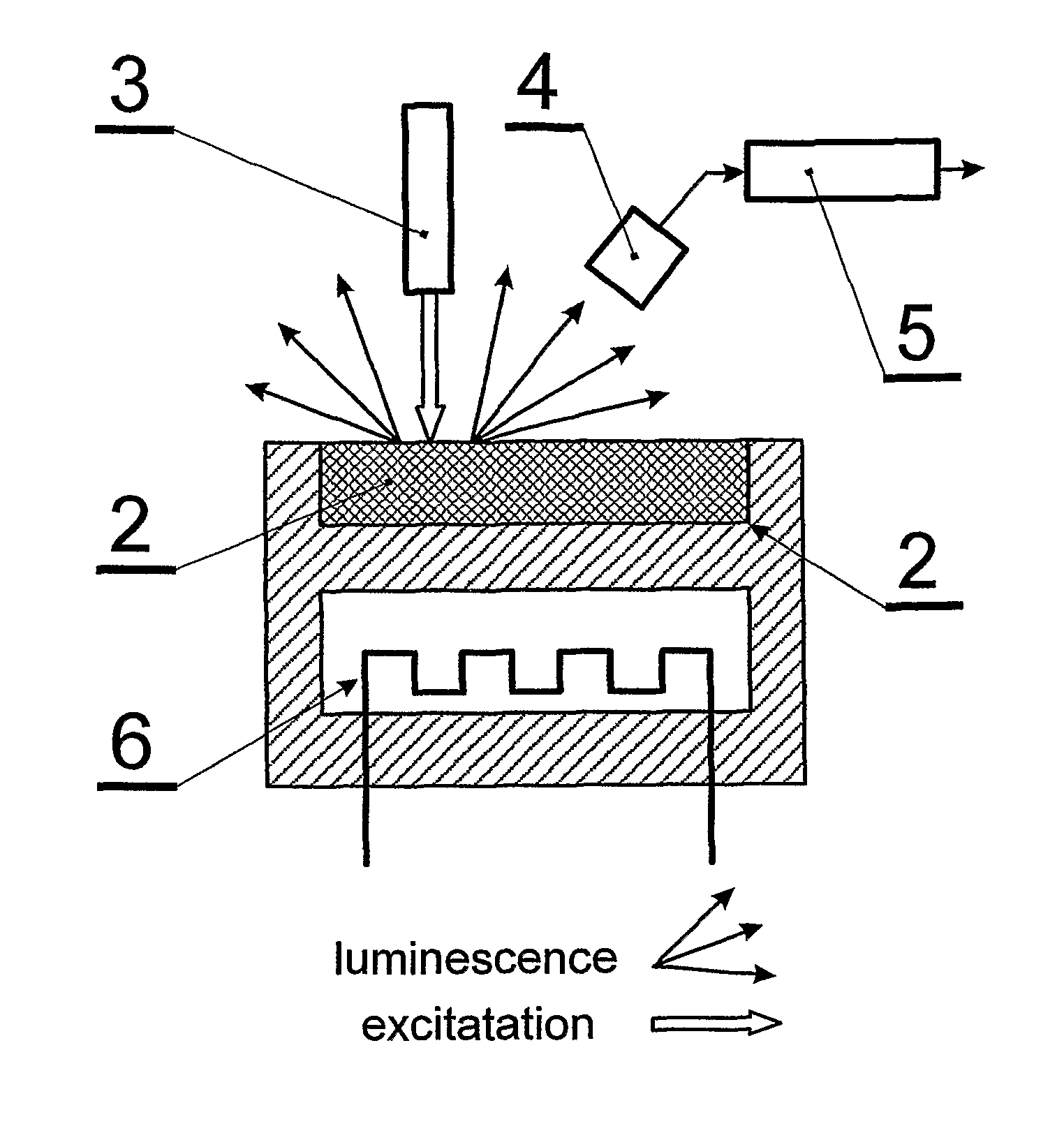
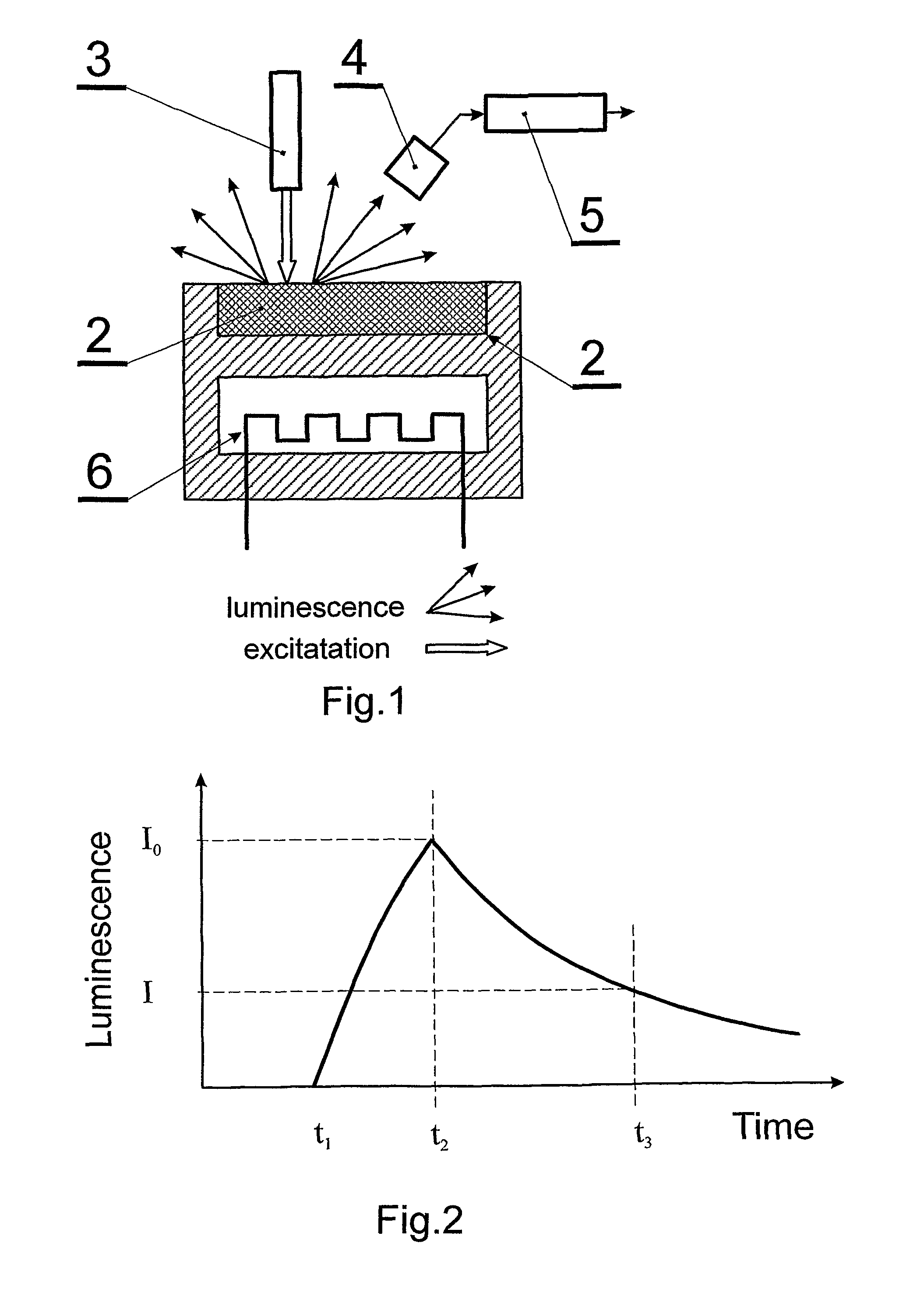
[0061]A measuring sensor 2 containing nanocrystalline zirconium dioxide, consisting of a stabilized tetragonal phase with an average size of crystallines 80 nm has been prepared, its calibration has been conducted, during which one has determined the thermal energy activation of the luminescence decay (Ea), parameter τ0, range of its work temperature, dependence of the luminescence intensity in the function of the oxygen pressure in this temperature range as well as the time of the luminescence decay in the temperature function, and then it has been placed in the sensor element containing metal chamber 1 and heated up to the temperature of 450° C. and the car exhaust fumes have been let in. Next, in time t0, the surface of the sensor contacting the measured gas has been illuminated by the inducing UV light pulse with LED 3 (280 nm), which excited the own luminescence in ZrO2 in the band 2.7 eV, which then was detected by the photodiode 4 (FDS 100) having signal rise—time 10 ns. The ...

example 2

[0062]A measuring sensor 2 containing nanocrystalline zirconium dioxide, consisting of a stabilized tetragonal phase with an average size of crystallines 15 nm has been prepared, its calibration has been conducted, during which one has determined the thermal energy activation of the luminescence decay (Ea), parameter τ0 range of its work temperature, dependence of the luminescence intensity in the function of the oxygen pressure in this temperature range as well as the time of the luminescence decay in the temperature function, and then it has been placed in the sensor element containing metal chamber 1 and heated up to the temperature of 200° C. and the analysed gas (mixture of nitrogen and oxygen) has been let in. Next in time t0, the surface of the sensor contacting the measured gas has been illuminated by the inducing UV light pulse with LED 3 (280 nm), which excited the own luminescence in ZrO2 in the band 2.7 eV, which then was detected by the photodiode 4 (FDS 100) of the gro...


PUM


Abstract

A method of measuring oxygen partial pressure in gases, such as hot engine exhaust gases, uses a calibrated luminescence sensor and comprises the steps of bringing nanocrystalline zirconium dioxide ZrO2 (2) in said sensor into contact with a gas to be measured, illuminating the zirconium dioxide with a UV-VIS light pulse emitted from a light source (3) and adapted to induce luminescence of the zirconium dioxide, registering the time dependence of the luminescence intensity of the ZrO2 using a photodetector (4) and a recorder (5), determining a particular intensity, e.g., the maximum intensity of the registered luminescence pulse, and comparing said determined intensity with calibration data of the luminescence intensity as a function of oxygen partial pressure for the sensor temperature at the time of the measurement.

Description

TECHNICAL FIELD[0001]The invention relates to method of measuring of partial pressure of oxygen in gases by measuring the excited luminescence of the sensor, especially applicable in the measurements of the oxygen amount in exhaust gases of car engines as well as in the control of technological processes, control of the oxygen level in glasshouses, lecture rooms, conference rooms, restaurants and in the optimization of combustion processes as well as in metallurgy.BACKGROUND ART[0002]The patent PL 142779 discloses a device for the constant measurement of the oxygen amount in hot gases, based on a method of the use of heat of catalytic reaction of oxygen with hydrogen, while from the U.S. Pat. No. 3,849,539 a method is known for marking and deoxygenation from an inert gas stream with regard to hydrogen.[0003]The method of measurement in accordance with the U.S. Pat. No. 3,849,539 cannot be used to determine the oxygen level directly in hot gases in view of the necessity of the initia...

Claims


Application Information

Patent Timeline
Patent Type & Authority Patents(United States)
IPC IPC(8): G01J1/58
CPCG01N21/6408G01N21/6489
Inventor LOJKOWSKI, WITOLDMILLERS, DONATSFIDELUS, JANUSZGRIGORIEVA, LARISAOPALINSKA, AGNIESZKANARKIEWICZ, URSZULASTREK, WIESLAW
Owner INST WYSOKICH CISNIEN POLSKIEJ AKADI NAUK
Why Eureka
Try Eureka